
Installation guide


EN | 35
D9124 | Operation & Installation Guide |
Bosch Security Systems | 11/03 | 39352E
8. Power Outputs
8.1 Auxiliary
All external connections at the D9124
motherboard are power limited.
8.1.1 12 V Auxiliary Power from D9412GLTB
Terminal 1
The D9124 supplies 1.4 A at 10.2 VDC to 14 VDC to
power auxiliary devices. A self-resetting circuit breaker
protects the circuit against shorts. Devices powered from
this output must operate within a range of 10.2 VDC to
14 VDC.
8.1.2 24 VDC Power from Motherboard Terminal 5
Use Terminal 5 to power smoke detectors or other
devices reset by interrupting power. Performing a
detector reset from the command center momentarily
interrupts 24 VDC power to Terminal 5 to reset the
smoke detectors.
Power Output Depends on Standby Time
Requirements
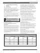
If your standby requirements call for 24-hour standby
time, the D9142 power supply provides up to 0.136 A at
Terminal 5 on the motherboard with 3 A of bell current
available for 5 minutes of alarm after a 24-hour period
of AC power loss. To increase this output, use larger
capacity batteries (up to 38 Ah) in an additional
enclosure (see Table 15).
If your application requires 60 hours of standby time,
the D9142 provides 0.030 A of standby current at
Terminal 5 on the motherboard. Also, 3 A of bell
current is available for 5 minutes of alarm after a
60-hour period of AC power loss. To increase this
output, use larger capacity batteries (up to 38 Ah) in an
additional enclosure (see Table 15).
See Section A.1.2 24 VDC Device Calculations for more
information about standby time and available power
output.
Total output power for the D9124 must
not exceed 4 A. The total output power for
auxiliary power (Terminal 5), and the 24 VDC
indicating circuits (Terminals 7 and 9) must
not exceed 4 A. Exceeding 4 A overloads the
D9142 power supply. See
A.1.2
24 VDC
Device Calculations
for more information.
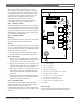
Verification/Sensor Reset Relay
Relay B is Terminal 7 on the D9412GLTB board.
Terminal 7 on the D9412GLTB controls the output at
Terminal 5 on the D9124 motherboard. When Relay B is
energized for detector reset or alarm verification, power
to Terminal 5 of the D9124 is interrupted.
See Area Parameters A# Verify Time, Point Indexes, and
Relay Parameters A# Reset Sensors in the D9412G/D7412G
Program Entry Guide for instructions on programming
verification/reset relays and points.
Pressing [DETECTOR RESET] activates verification/
reset relays for 5 seconds. The control panel ignores the
verification/reset points while the relay activates.
8.2 Alarm Power Output for Indicating
Circuits
8.2.1 24 VDC Output Terminals 7 and 9
Each Alarm Power Output Terminal (7 and 9) on the
motherboard provides 24 VDC, 1.8 A maximum of
alarm power output for bells, sirens, piezo fire sounders,
and electronic horns and strobes. Current calculations in
Table 15 are based on a 3 A maximum.
Total output power for the D9124 must
not exceed 4 A. The total output power for
auxiliary power (Terminal 5), and the 24 VDC
indicating circuits (Terminals 7 and 9) must
not exceed 4 A. Exceeding 4 A overloads the
D9142 power supply. See
A.1.2
24 VDC
Device Calculations
for more information.
8.2.2 Alarm Power Output Responses
Programming in the Bell Parameters, Point Index
Codes, Point Assignments, and Relay Parameters
determines the responses of Terminals 7 and 9. See the
D9412G/D7412G Program Entry Guide for programming
instructions.
Relay A is Terminal 6 on the D9412GLTB. Terminal 6
on the D9412GLTB controls the output at Terminals 7
and 9 on the D9124 motherboard. Energizing Relay A
provides power to Terminals 7 and 9 on the
motherboard. The default program sets Relay A for A#
Fire Bell. There is no need to reprogram the relay.
8. Power Outputs