
Installation guide


Bosch Security Systems | 11/03 | 39352E
EN | 34
D9124 | Operation & Installation Guide |
7. Power Supplies
7.2 24 VDC Initiating and Indicating
Devices
7.2.1 Primary Power
The D1601 is a 120 VAC, 16.5 V/24 VAC dual
secondary transformer, which is the primary power
supply for the control panel and initiating devices of the
D9124. See Section 3.5 Installing the D1601 Transformer
for more information about installing the D1601.
7.2.2 Secondary Power
Secondary power for the alarm indicating devices (such
as bells, horns, and strobes) is supplied by two D126
12 V, 7 Ah sealed lead-acid rechargeable batteries or up
to two external D1218 12 V, 17.2 or 18 Ah sealed lead-
acid rechargeable batteries (or larger) in a separate
enclosure.
When connecting two D1218 Batteries to
the control panel, both must have the same
capacity (use two 17.2 Ah batteries or two
18 Ah batteries).
Replace batteries every 3 to 5 years under normal use.
Use only lead acid batteries.
Choosing the Right Batteries to Meet 24 V
Requirements
The correct size of batteries connected to the system
depends on the amount of current the devices draw from
the power supply and the standard you are meeting.
Table 15 contains examples of the amount of current the
24 VDC devices can draw, depending on the battery
Ampere-hours you installed and the amount of standby
time you need. The calculations for Table 15 include
current requirements for 5 minutes of bell time at the
end of the standby period.
For example, if you have 7 Ah of battery capacity (two
D126 batteries installed) and you need to provide
24 hours of standby time, the 24 VDC devices may
draw no more than 0.135 A. In addition to the 0.135 A
of continuous current drawn, you can also attach up to 3
A of indicating devices (bells for up to 5 minutes) to the
Bell Circuit terminals on the motherboard.
The maximum standby current cannot exceed 1.5 A, the
maximum bell current cannot exceed 3 A, and the total
current cannot exceed 4 A. See Section A.1.2 24 VDC
Device Calculations for more information.
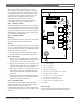
Installing the 24 V Standby Source Batteries
See Section 3.3 Safety before installing batteries.
1. Place the batteries on the top battery shelf.
2. Connect the black negative wires from battery
harness P7 to the negative terminals on the batteries.
3. Connect the red wires from battery harness P7 to
the positive terminals on the batteries.
4. Plug battery harness P7 into Connector J7 on the
D9142 power supply.
D9142 24 VDC Power Supervision
The float charge voltage for the battery charging circuit
is 27.6 VDC. When the float charge drops to a low
battery condition, or when the batteries are removed, the
red LED on the power supply illuminates. The D9142
sends a Tbl Point 8 Report to the receiver, Point 8
displays a trouble at the command center. Investigate
low battery reports immediately.
Circuit Protection
The power supply limits current output to 4 A. It is
protected against reversed battery polarity, thermal
overload, and current overload with a self-resetting
current limited circuit.
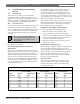
Table 15: Examples of Standby Power Requirements (24 V Devices)
24-Hour Standby 60-Hour Standby 72-Hour Standby
Battery
Amp-Hours
Current
(A)
Recharge Time
(Hrs.)
Current
(A)
Recharge Time
(Hrs.)
Current
(A)
Recharge Time
(Hrs.)
7 0.136 10 0.030 12 0.012 12
12 0.322 10 0.105 12 0.075 12
14 0.397 11 0.135 12 0.100 12
17.2 0.517 13 0.183 14 0.140 14
24 0.771 18 0.286 18 0.225 18
36 1.219 34 0.467 27 0.376 26
38 1.294 37 0.497 29 0.401 28