
Installation guide


Bosch Security Systems | 11/03 | 39352E
EN | 32
D9124 | Operation & Installation Guide |
Installing the 12 V Standby Source Batteries
When connecting two batteries, connect them in
parallel. Before handling the batteries, see Section 3.1
Safety for important information.
1. Place the batteries on the bottom shelf. The longer
set of leads from the battery harness connects to the
battery on the right side of the battery shelf.
2. Connect the black negative wires from the battery
harness to the negative terminals on the batteries.
3. Connect the red wires from the battery harness to
the positive terminals on the batteries.
High-current arcs are possible. The positive
(red) battery lead and Terminal 5 can create
high-current arcs if shorted to other terminals
or the enclosure. Use caution when working
with the positive lead and Terminal 5. Always
disconnect the positive (red) lead from the
battery before removing it from Terminal 5.
Adding Additional Power Supply and Batteries
D8132 boosts battery backup. Adding a
D8132 Battery Charger Module supports
additional batteries of up to 36 Ah capacity,
if required.
In applications where the supervision of two
batteries is required, you must use a D113
Battery Supervision Module.
Use the D8132 Battery Charger Module to connect two
additional batteries for a total of four. The control panel
plus any connected D8132 Modules and AUX power
supplies must be on the same AC circuit for discharging
evenly if AC power fails. The number of D8132
Modules is determined by the number of available
outlets on the same circuit. See Table 15 for battery
standby time calculations.
Replacing the Battery
Replace batteries every 3 to 5 years under normal use.
Exceeding the maximum output ratings causes heavy
discharges. Routine heavy discharges can lead to
premature battery failure. Record the date of installation
directly on the battery.
Battery Supervision
When battery voltage drops to 13.8 VDC, the yellow
Charging Status LED lights. When the battery drops to
12.1 VDC, the red Low Battery LED lights and the
control panel, if programmed for power supervision,
transmits a Battery Low Report in the Radionics’
Modem IIIa
2
Communication Format. It transmits a
Trouble ZN 9 Report in the BFSK format.
If the battery is missing or shorted, the red Low Battery
LED flashes at the same rate as the green Operation
Monitor LED. If the control panel is programmed for
power supervision, it transmits a Battery Missing Report
in the Modem IIIa
2
format, or Trouble ZN 9 Report in
the BFSK format.
When battery voltage returns to 13.7 VDC, the Low
Battery LED goes out. If the control panel is
programmed for power supervision, it transmits a
Battery Restoral Report in the Radionics’ Modem IIIa
2
Communication Format or Restoral ZN 9 Report in the
BFSK format. At 13.9 VDC, the Charging Status LED
goes out.
Investigate low battery reports immediately. If
primary (AC) power is off and the discharge
continues, the control panel becomes
inoperative when the battery voltage drops
below 10.2 VDC.
Battery Charging Circuit
The float voltage for the battery charging circuit is
13.5 VDC to 13.9 VDC at a maximum current of 1.4 A.
If float voltage drops below 13.5 VDC, the Charger
LED illuminates.
Loss of AC Load Shed Relay protects
batteries. During an AC power loss, the
batteries supply all power to the D9124
control panel. If the battery voltage falls
below 10.2 V during an AC power loss, a
load shed relay isolates the battery from the
control panel and disables the control panel.
Load shed protects the battery from being
damaged by deep discharge. When AC
power restores, the load shed relay resets
and battery voltage is again available.
Overcharge load shed with AC present. If
more than 1.4 A of current draw from the
control panel is detected, the control panel
shuts down. Remove all loads to the control
panel and disconnect AC power. Add a new
battery and reconnect AC power.
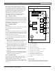
Reset the control panel by momentarily placing the
Reset pin in the disable position (Figure 8). The red Low
Battery LED continues flashing until you reset the
control panel.
A shorted battery condition is created by a shorted cell
inside the battery or by a short on Terminals 4 and 5. A
shorted battery may generate Watchdog Reset Reports.
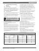
See Table13 for the battery discharging and recharging
cycles. Table 14 identifies and defines the Charging
Status and Low Battery LEDs.
7. Power Supplies