
Installation guide


EN | 31
D9124 | Operation & Installation Guide |
Bosch Security Systems | 11/03 | 39352E
7. Power Supplies
7.1 D9412GLTB, Command Center, and
Modules
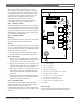
7.1.1 Primary Power
Primary (AC) Power Circuit
A 16.5 VAC/24 VAC dual secondary transformer (Bosch
Security Systems Model D1601) is the primary power
source. The AC power circuit provides 1.9 A of rectified
AC power. The control panel reserves 500 mA of this
power for internal operations, leaving 1.4 A for powered
devices.
Transient suppressors and spark gaps protect the circuit
from power surges. This protection relies on the ground
connection at Terminal 10. Make sure Terminal 10 is
connected to a proper ground. See Section 3.4 Connecting
the Earth Ground.
AC Power Failure
The system indicates an AC power failure when the
power at Terminals 1 and 2 is missing. The AC Fail
Time program item sets the number of minutes AC
must be missing before the control panel acknowledges
the failure and the number of minutes after the power
returns before the control panel acknowledges the
restoral of power.
You can program AC Fail Time from 1 second to 90
minutes. The Bosch Security Systems default sets AC
Fail Time at 82 seconds.
7.1.2 Secondary Power
Two 12 V, 7 Ah (up to 14 Ah) sealed lead-acid
rechargeable batteries (D126) or two 12 V, 17.2 or 18 Ah
(up to 34.4 or 36 Ah) sealed lead-acid rechargeable
batteries (D1218) supply secondary power for the control
panel, the command centers, auxiliary and alarm
outputs, and powers the system during interruptions in
primary (AC) power.
When connecting two D1218 Batteries to
the control panel, both must have the same
capacity (use two 17.2 Ah batteries or two
18 Ah batteries).
In applications where the supervision of two batteries is
required, you must use a D113 Battery Supervision
Module.
Only use lead-acid batteries. The charging
circuit is calibrated for lead-acid batteries.
Do not use gel-cell or nicad batteries.
Choosing the Right Batteries to Meet 12 V
Requirements
To determine the correct battery size connecting to the
system, you must know the amount of current the 12 V
devices draw from the D9412GLTB. You also must know
number of hours the batteries are expected to last. Refer
to 12 VDC Device Calculations in Appendix A: Determining
Battery Requirements for worksheets of the actual
calculations that must be performed to determine the
current draw for your installation and the UL and
NFPA standby battery requirements for your
application.
Dual batteries are required for fire applications.
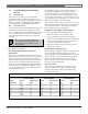
Table 12 contains examples of the impact of adding 12 V
devices while meeting UL and NFPA requirements for
fire detection systems.
Table 12
is for illustrative purposes only. You
must perform actual calculations to
determine the requirements for your
installation and application.
7. Power Supplies
Table 12: Examples of Standby Power Requirements (12 V Devices)
Battery or Power Supply RequirementsSystem Includes Column B
Total (mA)
Column C
Total (mA)
24-Hour Standby 60-Hour Standby
D9124 only 562 874 One D1218
Additional power supply and
batteries
D9124 + command center 668 1080 Two D1218s
Additional power supply and
batteries
D9124 + command center +
119 POPITs
1025 1556 Two D1218s
Additional power supply and
batteries
D9124 + D8125 + 238
POPITs + command center
1430 2080
Additional power supply and
batteries
Additional power supply and
batteries