
Installation guide


Bosch Security Systems | 11/03 | 39352E
EN | 30
D9124 | Operation & Installation Guide |
6. ZONEX Addressable Points
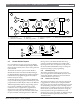
1 - Motherboard 2 - D9127P/U POPIT 3 - Data loop positive 4 - Data loop negative
Figure 20: Connecting Heat Detectors and Other Mechanical Devices
+
-
1
2 2
2
3
4
6.7 Central Station Reports
For a complete list of reports received by the D6600
receiver, refer to the D6600 Computer Interface Manual.
Reports from the D9124 are the same as those generated
by the D9412G.
The D9124 can transmit reports in either BFSK or
Modem IIIa
2
formats. See Phone and Phone Routing of
the D9412G/D7412G Program Entry Guide for important
information about programming phone transmission
formats and report routing.
If a POPIT disconnects from the D8125 POPEX Data
Loop, a Trouble message appears immediately for points
programmed for Trouble Reports. Refer to the D9412G /
D7412G Program Entry Guide for programming options.
If you connect a POPIT programmed for a point
number that does not appear in the program for the
D9124 System to the D8125 POPEX Data Loop, it
appears as an extra point at the command centers when
the point is faulted, and during the Service Walk Test.
Placing a short on the D8125 POPEX Data Loop
generates a PT Bus Trouble Report (in Modem IIIa
2
reporting format). The control panel sees all points on
the shorted D8125 POPEX Data Loop as missing and
responds according to point programming.
6.7.1 BFSK Reporting
The number transmitted when an event occurs on a
point is programmed in P### BFSK Rpt Code, Point
Assignments Module. This format sends summarized
system information to the receiver.
6.7.2 Modem IIIa
2
Reporting
The actual point number is sent when the control panel
is programmed to transmit reports using the Modem
IIIa
2
format. You can program the D9124 System to send
an additional flag with point reports. This flag tells the
D6600 receiver to translate point and user numbers to a
Bosch Security Systems D8112 style format. Using this
feature depends on the type of automation system
attached to the receiver. For details, see Point/User Flag in
the D9412G/D7412G Program Entry Guide, Phone
Parameters section.
Figure 19: Connecting Four-Wire Smoke Detectors
+
-
+
-
+
-
+
-
1
1
2
3
4
5
6
6 6
7
6
1 - Motherboard 3 - Common 5 - Data loop negative 7 - D294 EOL Supervision Relay
2 - Switched + 24 VDC 4 - Data loop positive 6 - POPIT