
Installation guide


EN | 29
D9124 | Operation & Installation Guide |
Bosch Security Systems | 11/03 | 39352E
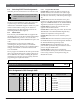
6. ZONEX Addressable Points
Table 11: Data Loops and POPITs
D8125 POPEX #1 D8125 POPEX #2
Data Loops 1 to 4 Data Loops 5 to 8
Points 9 to 127 Points 129 to 247
1 - D9127U/T 4 - POPIT switch block (typically up to 119 places)
2 - POPIT sensor loop (typically up to 119 places) 5 - To motherboard D8125 POPEX data loop
3 - 33 k
Ω
EOL resistor (typically up to 119 places) 6 - Up to 119 POPITs
Figure 17: Connecting POPITs to Data Cable
5
(-)
(+)
1 1 1
6
(–)
(+)
2 3
2
3
3
2
444
6.6 Wiring the POPIT Sensor Loop
POPIT Modules monitor their sensor loops for three
conditions: Loop Normal, Loop Open, and Loop
Shorted. They report these three conditions to the
D9124 System.
The D9124 System uses point programming to interpret
the sensor loop information reported by the POPITs
and make the appropriate system response.
Terminate all POPIT sensor loops with a 33 kΩ EOL
resistor, Bosch Security Systems Model D106F, supplied
with each POPIT Module. See Figures 19 and 20.
6.6.1 POPIT Displays
For a list of D1255, D1256, and D1257 displays, refer to
the User’s Guide provided with the command center or
fire alarm annunciator.
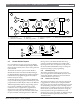
Figure 18: Connecting Devices to the Motherboard
+
-
+
-
+
-
+
-
+
-
+
-
+
-
+
-
1
2
3
4
5
6
7
7
66
1
1 - Motherboard 3 - Common 5 - Data loop negative 7 - To next
2 - Switched + 24 VDC 4 - Data loop positive 6 - D291M/D291S base