
Installation guide


Bosch Security Systems | 11/03 | 39352E
EN | 28
D9124 | Operation & Installation Guide |
6. ZONEX, Addressable Points
6.4 Installing POPITs
Each POPIT comes with an installation card. You
should be familiar with the POPIT installation card
before attempting to install POPITS.
6.4.1 Routing the Data Cable
The two-wire data expansion loop connects POPIT
Modules assigned to a single D8125 POPEX. You can
connect up to four data loops to one D8125 at the
motherboard. Data Loops 1 to 4 connect to D8125
POPEX #1. Data Loops 5 to 8 connect to D8125
POPEX #2 (Figure 14).
Total resistance of the D8125 POPEX Data
Loops cannot exceed 60
Ω
regardless of
wire gauge or distance used. To estimate
resistance, refer to
Table 10
.
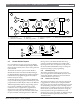
To determine total resistance, tie the ends of the D8125
POPEX Data Loops together to eliminate POPIT
resistance (Figure 16). After measuring resistance, untie
the ends of the D8125 POPEX Data Loops.
Electromagnetic interference (EMI) may
cause problems. If you suspect EMI is
a problem, refer to
Section 12.9 EMI on
Long Wire Runs
.
Figure 16: Checking Resistance of Data Loops
1 - POPIT 3 - 60
Ω
maximum
2 - Ohmmeter 4 - Short ends together (testing only)
Ω
1
2
3
4
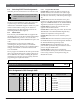
Table 10: Resistance by Wire Size
Wire Size
AWG mm
Ω
per 305 m (1000 ft.)
12 2.3 1.62
14 1.8 2.58
16 1.5 4.09
18 1.2 6.51
20 1.0 10.40
22 0.8 16.50
6.4.2 Connect POPITS to the Data Cable
You do not need to wire POPIT Modules in any order
on the motherboard D8125 POPEX Data Expansion
Loop. An address setting on each POPIT (Section 6.3
Selecting POPIT Point Assignments) identifies the point of
protection, regardless of its physical location on the data
cable. POPIT Modules must be mounted at least 7.6 cm
(3 in.) apart and using at least 15.2 cm (6 in.) of wire.
This prevents the tamper magnets from interfering with
each other.
Connect POPIT Modules to the data loop in parallel.
Do not T-tap POPIT Data Loops together (Figure 17).
1. Connect the positive (+) data terminal from one
POPIT to the positive (+) data terminal on the next
POPIT.
2. Connect the negative (-) data terminal from one
POPIT to the negative (-) data terminal on the next
POPIT.
3. Repeat Steps 1 and 2 to connect all POPITs on the
same D8125 POPEX Data Loop.
6.4.3 Connecting the D291S and D291M
Addressable Smoke Detector Bases
To prevent damage to the POPEX module,
wire smoke detector bases when the data
cable is disconnected from the motherboard.
Before connecting detector wiring to the
control panel, meter each wire to ground to
check for continuity, and meter between
each wire for continuity. You should have no
grounds or shorts between any of the wires.
Put the detector heads on after you have
metered all the wiring (
Figure 18
).
Before beginning the installation, refer to the
Operation and Installation Guides
for these
detectors.
6.5 Connecting Data Loops to Terminals
on the Motherboard
D8125 POPEX modules must have their
own data expansion loops. The motherboard
provides two sets of D8125 POPEX Data
Loops. POPIT modules assigned to D8125
POPEX #1 cannot be placed on the D8125
POPEX #2 Data Loop. Limit the data loops
returning to the motherboard to a maximum
of four data loop runs for each POPEX you
install. See
Table 11
.