
Installation guide


EN | 27
D9124 | Operation & Installation Guide |
Bosch Security Systems | 11/03 | 39352E
6.3 Selecting POPIT Point Assignments
Off-board points are numbered 9 to 127 and 129 to 247.
The D9124 System reserves points 128 to
248 for internal use to supervise the data
loops.
You must connect POPITs for points 129 to 247 to the
expansion loops connected to D8125 POPEX #2.
Addresses for each POPIT assign the module to a point
number. POPIT address settings are in Section 6.3.1
POPIT Labels and the Point Assignments section of the
D9124 Program Record Sheet (Figure 15).
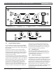
6.3.1 POPIT Labels
Four sheets of peel-off POPIT labels are supplied with
the D9124 System. Use the sheet marked Vertical Grid for
D8125 POPEX #1 for points 9 to 127. Use the sheet
marked Vertical Grid for D8125 POPEX #2 for points 129
to 247.
Each label has two parts. Place the smaller part
(containing only the point number) on the POPIT
terminal block. Place the larger part (containing address
settings) on the POPIT cover. Set the addresses and
cover the POPIT.
Do not program two POPITs for the same point number.
After you program all the points, perform a Fire Test or
Service Walk Test. See Section 11.0 Testing the System for
instructions. If a point does not test properly, check the
programming for a duplicated address.
6. ZONEX, Addressable Points
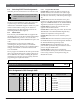
6.3.2 Program Record Sheet
Column One: Contains the address settings for the
POPITs. Addresses are numbered 0 to 6, left to right.
Set addresses whose number appears in the ON position.
Set addresses with a dash (-) in the OFF position (Figure
15).
Column Two: Contains the translation of the point
number into the D8112 ZONEX format. See Point/User
Flag in the 9000MAIN Module of the D9 412G/ D7412G
Program Entry Guide for an explanation of this feature.
Column Three: Contains the point number as it
appears at the command centers.
Column Four: Contains the point index. See the Point
Index Module in the D9412G/D7412G Program Entry
Guide for an explanation of the point index.
Column Five: Shows the area to which the point is
assigned.
Column Six: Shows the Debounce Count for the point.
See P### Debounce in the Point Assignments Module of
the D9412G/D7412G Program Entry Guide.
Column Seven: Shows the BFSK report code, the
point number reported for this point when the control
panel is using the BFSK format.
Column Eight: Contains the text displayed at
command centers for the point. The text is transmitted
to the receiver when the control panel is using the
Modem IIIa
2
format.
Figure 15: Program Record Sheet
D9412G/D7412G |
Program Record Sheet | RADXPNTS Handler
EN
| 24
RADXPNTS Handler
Default values are shown in ( ) or in
bold
Point Assignments (001 through 040)
POPIT Switch
Setting
Trans-
lation
Point
#
Point
Index
Area
Assign
Debounce
BFSK/
Relay
Custom Point Text
100 001 (3) _ _ (1) ___ (2) _____ (1) ____ P1 FIRE ___________________
200 002 (1) _ _ (1) ___ (2) _____ (2) ____ P2 PANIC ___________________
300 003 (25) _ _ (1) ___ (2) _____ (3) ____ P3 DELAY ___________________
400 004 (13) _ _ (1) ___ (2) _____ (4) ____ P4 FOLLOW ___________________
500 005 (7) _ _ (1) ___ (2) _____ (5) ____ P5 INSTANT ___________________
600 006 (7) _ _ (1) ___ (2) _____ (6) ____ P6 INSTANT ___________________
700 007 (7) _ _ (1) ___ (2) _____ (7) ____ P7 INSTANT ___________________
800 008 (7) _ _ (1) ___ (2) _____ (8) ____ P8 INSTANT ___________________