
Installation guide


EN | 25
D9124 | Operation & Installation Guide |
Bosch Security Systems | 11/03 | 39352E
6. ZONEX, Addressable Points
6.1 Description
You can use POPIT Modules to provide up to 238
off-board points, bringing the total number of points the
D9124 System can monitor to 246. Each off-board point
requires a POPIT Module.
POPITs connect to supervised two-wire data expansion
loops run from POPIT to POPIT throughout the
premises (Figure 14). Data expansion loops connect to
the motherboard. The motherboard connects to the
POPEX Module. POPEX Modules connect to the point
bus on the control panel.
You can connect up to four data expansion loops to one
D8125 input at the motherboard. Data Loops 1 to 4
connect to the D8125 POPEX 1 input on the
motherboard (Terminals 11 through 18). Data Loops 5 to
8 connect to the D8125 POPEX 2 input at the
motherboard (Terminals 19 through 26).
If a POPIT is disconnected from the expansion loop, a
trouble message appears immediately. See the D9 412G/
D7412G Program Entry Guide for programming options.
Placing a short on the data expansion loop generates a
PT Bus Trouble Report. The control panel sees all points
on the shorted expansion loop as shorted and responds
according to point programming. The fire points
respond locally as a Trouble condition and transmit
Missing Fire Reports if programmed during this
condition.
POPIT Modules monitor their sensor loops for three
conditions: Loop Normal, Loop Open, and Loop
Shorted. They report these three conditions to the
control panel.
The D9124 uses point programming to interpret the
sensor loop information reported by the POPITs and
makes the appropriate system response. Initiation
devices connect to each POPIT. The POPIT sensor
loop can supervise an unlimited number of initiation
devices. Certain applications can limit the number of
initiation devices. Consult the appropriate NFPA
standards.
The POPIT comes in a tampered enclosure (D9127T) or
an untampered enclosure (D9127U).
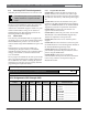
Verify the proper setting of motherboard jumpers:
Make sure the jumpers above Terminals 18 to 24 on the
motherboard are in the D8125 position (Figure 13).
6.1.1 POPEX/POPIT Configurations
With the D8125 POPEX Module, you can:
• use D8125 POPEX 1, data loops 1 to 4 (Terminals
11 to 18) on the motherboard (Figure 14).
• install a maximum of 119 POPITs (Points 9 to 127).
• use Points 7 and 8 for power supply and initiation
circuit supervision. POPITs are not required for
these functions.
With an additional D8125 POPEX Module, you can:
• use D8125 POPEX 2, data loops 5 to 8 (Terminals
19 to 26) on the motherboard (see Figure 14).
• install an additional 119 POPITs (Points 129 to 247)
for a maximum of 238 POPITs in the system.
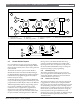
6.2 Connecting the Additional D8125
Module
1. Mount the module to a D138 mounting bracket,
using only the three screws provided.
2. Mount this assembly in the empty slot next to the
other modules on the Accessory Module Carrier.
Use the orientation of the other modules as a guide.
See Figure 2.
3. Connect the clip-on end of the extra wiring harness
to the far right connector (J5) on the motherboard.
4. Connect the hanging wires to the D8125 Module as
shown in Table 9.
6. ZONEX, Addressable Points
Figure 13: D8125 Jumper Setting
1 - Jumpers set in the D8125 position.
J9
17 18 19 20 21 22 23 24 25 26
J9 J8 J7 J 1 2 J11 J 1 0
P5
1