
Installation guide


EN | 23
D9124 | Operation & Installation Guide |
Bosch Security Systems | 11/03 | 39352E
5. Indicating Circuit (24 VDC
Horns/Strobes/Bells)
5.1 Description
The D192C or D192G Indicating Circuit Module
supervises the wiring from the control panel to remote
alarm indicating devices like horns, strobes, and bells.
Wiring is supervised for open, shorted, or grounded
circuit faults.
Signaling devices must:
• be polarized (DC).
• match the voltage rating of the alarm power supply
(D9142).
• not exceed the current rating of the alarm power
supply (D9142).
• not exceed 1.8 A on motherboard Terminals 7 or 9
when combined.
Total output power for the D9124 system
must not exceed 4 A. The total output power
for auxiliary power (Terminal 5) and 24 VDC
indicating circuits (Terminals 7 and 9) must
not exceed 4 A. Exceeding 4 A overloads the
D9142 power supply. See
A.1.2
Calculations for 24 VDC Devices
to
determine total output requirements.
5.2 Operation
During normal operation, the indicating circuit is
supervised for incorrectly installed devices, opens,
shorts, and grounds. If any of these conditions are
detected, the control panel indicates a Trouble condition
at the command center. You can program the control
panel to report the condition to the central station.
When the control panel detects an alarm, the alarm
output circuit triggers the D192C or D192G to supply
circuit power from the power supply.
To provide supervision, install the 560 Ω, 2 W EOL
resistor (P/N: 15-03130-005) beyond the last indicating
device. Two resistors are supplied in the literature
package.
5. Indicating Circuit (24 VDC Horns/Strobes/Bells)
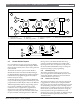
5.3 Silence Switch
The D192C or D192G has a toggle switch to disable the
fire alarm indicating devices while you test the control
panel (Figure 12). When this switch is toggled up in the
SILENCE position, the D192C or D192G presents a
short circuit to Point 7, causing a Trouble response.
Figure 12: D192/D192G Bell Silence Switch