
Installation guide


EN | 21
D9124 | Operation & Installation Guide |
Bosch Security Systems | 11/03 | 39352E
4. Command Centers and Annunciation Devices
4.3 Installing Command Centers and
Annunicators
A four-wire flying lead is required for the data and
power connections between the D1255, D1255R, D1256,
and motherboard. They come with a wiring assembly
consisting of four color-coded flying leads and a female,
four-pin connector plug at one end.
1. Using a small, flat-bladed screwdriver, gently push in
the two bottom tabs of the command center
enclosure cover. As you push back the tabs, lift the
command center cover away from the base.
2. Set the address settings as shown in Table 7. For
supervised command centers, assign only one to
each address.
3. Turn the command center over and plug in the
wiring connector through the opening in the back of
the enclosure base.
4. Mount the command center base in the desired
location and secure it using the mounting holes
inside the enclosure base.
5. Replace the cover. Align and insert the top two tabs
of the enclosure cover into the top two tab slots of
the enclosure base. Hold the top edges of the
enclosure cover and base in position. Push the tabs
inward and press the enclosure and cover together
until the cover snaps into place.
6. Press each key on the keypad toward the top of the
command center to ensure proper alignment and
operation of each key through the mating keypad
faceplate openings.
7. Install the locked cover according to the instructions
provided.
The remote command centers have lockable
covers. Protect remote command centers
with a locked cover such as the Safety
Technology’s 6550 Wide Body Keypad
Protector.
8. Connect the flying leads of the wiring assembly
(provided) to the wires from the panel (see Table 8).
Table 7: Command Center Address Settings
Address
Switch
1 2 3 4 5 6 7 8
1 ON OFF ON OFF ON OFF ON OFF
2 ON ON OFF OFF ON ON OFF OFF
3 ON ON ON ON OFF OFF OFF OFF
4
Leave ON – Do
not
use
5 Encoding Tone ON/OFF
6 Leave ON – Factory Test
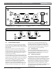
Switching the green and yellow wires affects
other command centers.
Incorrectly connecting the green wire from
the command center to the motherboard
Terminal 4 and the yellow wire to Terminal 3,
causes other command centers connected
to the control panel to go blank and/or
sound random tones.
You can connect a maximum of 4.6 km (15,000 ft.) of
22 AWG (0.8 mm) wire for all command centers and
printer modules combined
to the data bus, Terminal
3, and Terminal 4 on the motherboard. You can connect
parallel wire runs from the D9124 System to each
device, run wire device to device, or combine the two.
However, limit the individual wire runs to command
centers to 0.61 km (2000 ft.).
Extra power is needed for more command
centers and annunciators. The D1255,
D1255R, D1256, and D1257 each draw
104 mA when idle. Each draws 206 mA with
the back lighting for the keys illuminated and
the sounder activated. Review
Section 7.0
Power Supplies
and
Appendix A.1
Auxiliary
Current and Standby Battery Requirements
to determine the total power output
requirements for your system.
You might need to add one or more UL Listed power
supplies for the number of command centers you want
to use.
D9124 and the additional power supplies
must share COMMON.
When using an additional power supply to
power command centers, the common from
the additional power supply must connect to
both command centers' common and the
common on the D9412GLTB board.
A stand-alone power supply powering any
device connected to the D9124 must also
be connected to a common terminal on the
D9124.
Wire Color Motherboard Terminal
Red 1 +12 VDC
Black 2 Common
Yellow 3 Serial Data Out
Green 4 Serial Data In
Table 8: Command Center Connections