
Installation guide


Bosch Security Systems | 11/03 | 39352E
EN | 18
D9124 | Operation & Installation Guide |
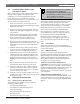
3. Installation
3.10 Wiring Additional Modules
Table 5 shows additional modules you can install with
the D9124 System, and where to connect module cables
to the D9124 System. Connect additional modules
(except for D8125 POPEX Modules) to the D9124
System as shown in Table 5. Refer to the module’s
Installation Instructions for remote device wiring. Table 5
shows only the connections to the D9124 System.
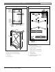
Route cables above the D9100 Accessory Module
Carrier to locations on the D9412GLTB. Space is
provided at the right side of the accessory module
carrier to route cables around and below the accessory
carrier to destinations on the motherboard and the
D9142 power supply. Use wire ties to bundle multiple
cables.
Do not pass cables through the D9100
Accessory Module Carrier. The carrier is
designed to protect enclosed modules from
EMI or other interference that can affect
module operation. Route all additional
module cables around the outside of the
Accessory Module Carrier.
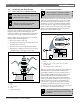
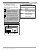
3.11 Turning on the Power
Before turning on the power, lock the Reset Pin (Figure
8) on the D9412GLTB. Locking the Reset Pin disables
the D9124 System. The panel ignores the command
centers and points while disabled. After power is
connected, CALL FOR SERVICE appears in command
center displays while the reset pin is locked down.
1. Lock the Reset Pin on the D9412GLTB (Figure 8).
2. Connect the two sets of batteries. Refer to Installing
the 12 V Standby Source Batteries and Installing the 24
V Standby Source Batteries in Section 7.0 Power
Supplies.
3. Turn the AC power on. The batteries begin to
charge, even though the D9412GLTB is still
disabled. The yellow LED on the D9412GLTB
illuminates if the batteries require charging.
Figure 8: Reset Pin
1 - Reset pin locked (closed)
2 - Reset pin normal (open)
PERIPHERAL DEVICE CONNECTIONS
Operation Monitor
Pulses When Normal
Flickers When Ringing
Solid When Held In Reset
RED
YELLOW
GREEN
BLACK
32
POWER +
DAT BUS A
DATA BUS B
COMMON
31
30
29
Reset Pin
Disable All Except Battery
Charging And Local Programming
GRN
1
2
Table 5: Wiring Additional Modules
D9124 Terminals
D125B
Terminal
D127
Terminal
D129
Terminal
D192C/G
Terminal
D8129
Terminal
D8130
Terminal
Motherboard TB1 1 (12 VDC) - 8 6 AUX AUX 3
Motherboard TB1 2 (COM) 4 and 10 1 and 3 8 COM GND 1
Motherboard TB1 3 (Data Out) - - - - - -
Motherboard TB1 4 (Data In) - - - - - -
Motherboard TB1 5 (Switched 24 VDC) 1 - - - - -
Motherboard TB1 6 (COM) 5 - 7 - - -
D9412GLTB TB2/3 Points 1 to 6 2 and/or 3 - 5 and/or 9 SUPV ZONE - 4
D9412GLTB TB1 6 (Alarm Output) - 9 or 10 - ALARM TRIG - 2
D9412GLTB ZONEX OUT - - -
- ZN1 OUT or
ZN2 OUT