
Installation guide


EN | 17
D9124 | Operation & Installation Guide |
Bosch Security Systems | 11/03 | 39352E
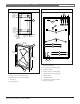
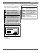
1 - D1256 Command Center 6 - D192C/G #1
2 - Cutaways for D192C/G Modules 7 - D192C/G #2
3 - Cutaway for D928 8 - D8125 POPEX #1 slot (module installed)
4 - D192C/G Indicating Circuit Supervision Modules 9 - D8125 POPEX #2 slot (optional)
5 - D928 Dual Phone Line Switcher 10 - D9142 power supply
Figure 7: Modules Installed on the Accessory Module Carrier
Q
Q
Q
1 2 3 4 5 6 7 8 9 10 11 12 13 14 15 16 17 18 19 20 21 22 23 24 25 26
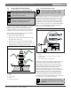
POPEX 1
D9124 LTB
Accessory Module Carrier
Maximum 24V DC output on terminals 5, 7 & 9
is 4 Amps.
Maximum 12V DC output on terminal 1 is:
240 mA for single POPEX systems
400 mA for dual POPEX system s.
The D8124G 2 system is delivered with a
single D812 5 POPEX installed (71poin ts). It
can be expanded with one additional POPEX
for a total of 134 system points.
POPEX 2
CIRCUIT 1 CIRCUIT 2
SILENCE
UP
DOWN
NORM AL
Signaling Circuit
Disable Switches
Signaling circuits must be
terminated wi th 560 ý 2 wa tt
EOL re sistors , Radion ics
Part Number 15-03 130-005.
19 20 21 22 23 24 25 2611 12 1 3 14 15 16 17 18
Q
Q
Q
POPEX 1
D9124 LTB
Accessory Module Carrier
Maximum 24 VDC output on terminals 5, 7,
and 9 is 4 A.
Maximum 12 VDC output o n terminal 1 is:
240 mA for single P OPEX systems
400 mA for dual POPEX system s.
The D8 124G2 s ystem is del ivere d with a
single D8125 POPEX installe d (71 points). It
can be expanded with one additional POPEX
for a total o f 134 system points.
POPEX 2
CIRCUIT 1 CIRCUIT 2
SILENCE
UP
DOWN
NORMAL
Signaling Circuit
Disable Switches
Signaling circuits mus t be terminated with
560 Ω 2 W E OL r esistors B osch Securit y
Systems (P/N: Number 15-03130-005).
19 20 21 22 23 24 25 2 611 12 1 3 1 4 15 16 17 18
1
2
3
4
5
6
7
8
9
10
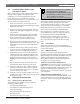
3.9 Connecting Cables Between D9124
System Components
Before you start, review Section 3.3 Safety.
Do not turn AC power on until instructed to
do so.
1. Make sure the dedicated AC power source is off. For
information about power specifications, refer to
Section 7.0 Power Supplies.
2. Connect the four terminal blocks to their locations
on the D9412GLTB, making sure each terminal
block clicks firmly into place.
3. Connect the flat ribbon cable between connector J4
on the D928 and connector J2 on the D9412GLTB.
For more information about the D928, see Section 9.0
Telephone Connections.
Do not force the cable in the wrong way. The
ends of the flat ribbon cable are keyed
so they only plug in one way.
4. If this is a communicating fire system, plug one end
of a D161 (20 cm [8 in.]) or D162 (5 cm [2 in.])
modular phone cord into J1 on the D928. Plug the
other end into the RJ31X (D166) for the primary
phone line and then plug one end of a D161 or
D162 phone cord into J2 on the D928. Plug the
other end into the RJ31X (D166) for the secondary
phone line.
5. Connect flying lead P1 into J1 (in the upper battery
shelf).
6. Verify transformer cable P8 is connected to J8 on
the lower left side of the D9142 power supply.
3. Installation