
Installation guide


Bosch Security Systems | 11/03 | 39352E
EN | 16
D9124 | Operation & Installation Guide |
3. Installation
3.7 Installing Battery Shelves and
Transformer Cover
Battery and transformer cables route through notches in
the upper battery shelf and the right side of the
transformer cover. The mounting hardware for the
battery shelf is taped to the shelf. The mounting
hardware for the transformer cover is taped to the cover.
To route cables and install the hardware:
1. Insert the connector for wire harness J1 into the
upper battery shelf so that the leads hang down from
the bottom of the shelf.
2. Loosely screw the four screws (provided with each
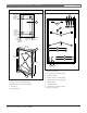
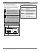
shelf) into the four shelf mounting holes. See Figure
2 for locations.
3. Route the cable connected to the transformer up,
and the battery cables down through the notch at
the back of the upper battery shelf. All wire
connections to J1 stay below the battery shelf.
4. Push the upper battery shelf back into place and
align the four holes in the shelf with the screws. Slip
the shelf down over the screws. Do not tighten the
screws yet.
5. Install the bottom battery shelf by loosely driving
the screws into the mounting flanges, slipping the
shelf over the screws, and tightening the screws.
6. Replace the protective cover over the transformer
while routing the battery cables through the notch
on the right side of the transformer enclosure cover.
Make sure the shrink wrapped circuit breaker is
outside the notch so it hangs over the lower battery
shelf.
7. Plug the transformer cable into J8 located on the
lower left-hand side of the D9142 power supply.
8. Inspect the notch in the battery shelf to verify the
transformer and battery cables route through and
have not slipped outside of the notch as you tighten
the screws on the battery shelf.
9. Verify the covers are securely installed over fuse F1
and TB1, and connector P8 is plugged into J8 on the
D9142 power supply.
3.8 Mounting the Components
3.8.1 D9100 Accessory Module Carrier
The D9100 Accessory Module Carrier includes the
following installed modules:
• One D8125 POPEX Module
• Two D192C or D192G Indicating Circuit
Supervision Modules
• One D928 Dual Phone Line Switcher
• One motherboard
• One D9142 24 VDC power supply
The D9142 was modified to be compatible
with the ground fault capability of a
D9412GLTB. The modified D9142 unit can
be identified by lot number 0200C or higher.
The lot number is located in the
upper right-hand corner of the control panel.
The Accessory Module Carrier also includes a D1256
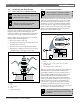
Fire Command Center. The right-hand side of the
carrier faceplate has three cutaway sections (see Figure
7). The one nearest the D1256 allows you to see the
D928 LEDs. The next two provide easy access to the
alarm switches on the D192C or D192G Modules.
The wiring harness is assembled at the factory, and
terminal blocks only need to be snapped into place in
the designated locations on the D9412GLTB.
Hang the accessory module carrier on the three
mounting hinges shown in Figure 2. Then secure the
three screws attached in the bottom three mounting
holes.
3.8.2 Control Panel
Hang the control panel on the two mounting hinges
shown in Figure 2. Secure the screw attached to the panel
in the mounting flange.
3.8.3 Additional Modules
The D9101 enclosure provides four locations for
mounting additional modules like the D192C or D192G
Bell Circuit Supervision Module, D125B Powered Loop
Interface, D129 Dual Class A Initiating Module, or
D8130 Release Modules on D138 mounting brackets.
See Figure 2 for mounting locations.
Additional modules affect standby battery
calculations. Due to increased power consumption, you
might need to increase the size of the standby batteries
attached to the D9412GLTB or D9142 power supply. See
Appendix A: Determining Battery Requirements to
determine the type and number of batteries you need for
your application.
Additional D8125 POPEX Module. If you are
installing an additional D8125 POPEX Module, install
it in the D9100 Accessory Carrier Module (Figure 7) as
described in Section 6.2 Connecting the Additional D8125
Module.