
Installation guide


EN | 15
D9124 | Operation & Installation Guide |
Bosch Security Systems | 11/03 | 39352E
3.0 Installation
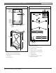
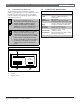
3.5 Installing the D1601 Transformer
Only route AC conduit into the enclosure
housing the D1601 Transformer.
The D1601 is a 120 VAC, 16.5 V/24 VAC dual
secondary transformer. It is the primary power supply
for the control panel and initiating devices of the D9124
System. Install the transformer in the lower left corner
of the D9101 enclosure (see Figure 6).
If the 120 VAC cabling for the transformer is
already installed, make sure the dedicated
circuit breaker for the system is off and route
the 120 VAC cables away from the
transformer mounting studs.
To install the D1601 Transformer:
1. Remove the hardware taped to the side of the
transformer. Do not leave any part of the plastic bag
or tape behind.
2. Place the star washers over the transformer studs in
the lower left corner of the D9101 enclosure (see
Figure 4).
3. Place the transformer over the star washers on the
four transformer mounting studs. Make sure the
transformer cables are routed up as shown in Figure
6.
4. Place the washers over the transformer mounting
brackets.
5. Place the nuts over the washers and tighten securely
into place.
3.6 Connecting the 120 VAC Power Input
Only use a licensed electrician to make 120 VAC
connections to the D9124 System. The electrician should
make all connections conforming to NEC 70 and
connect the D9124 System to a suitable ground
connection.
To connect the 120 VAC service to the D9124:
1. If the 120 VAC cabling is already installed, go to
Step 5. If the 120 VAC cabling is not already
installed, go to Step 2.
2. Make sure the incoming high voltage (120 VAC)
from the D9124 is disconnected.
Turn off the circuit breaker before connecting
the 120 VAC to the system. Leaving the
circuit breaker on can cause injury or death
by electrocution.
3. Remove the knockout cover on the lower left side of
the D9101 Enclosure and install the appropriate
hardware for connection to conduit.
4. Pull the 120 VAC power wires through the conduit
hardware installed in the knockout, and into the
transformer enclosure.
5. Refer to Section 3.4 Connecting the Earth Ground.
Using appropriate hardware, connect wires to the
flying leads from connector J1 as shown in Table 4.
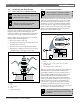
6. After the AC power is tied in, install the red metal
oxide varistor across the HOT and GND Terminals
of the 110 VAC Power Input of the D9142.
Table 4: High Voltage (120 V) Connections to the
D9124 System
Wire From 120 V Service Connect to D9124 System On
Green Ground stud below D1601
White White (on J1)
Black Black (on J1)
Figure 6: D1601 Installation