
Installation guide


EN | 13
D9124 | Operation & Installation Guide |
Bosch Security Systems | 11/03 | 39352E
3. Installation
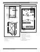
3.2.1 Flush Mounting
1. Cut and frame an opening measuring 56.75 cm x
92.25 cm x 7.75 cm (22.25 in. x 36.25 in. x 3 in.) to
accept the enclosure base box. See Figure 1.
2. Remove the door from the enclosure.
3. Remove the necessary knockouts for external
connections. See Figure 1.
4. Mount the enclosure in the framed opening using all
four mounting holes.
5. Run the necessary wiring throughout the premises
and pull the wires into the enclosure. A single
knockout is provided at the top right side of the
enclosure. If you punch other holes, do not let them
interfere with the component mounting locations.
3.2.2 Surface Mounting
1. Remove the door from the enclosure.
2. Remove the necessary knockouts for external
connections. See Figure 1.
3. Mount the enclosure in the desired location using
all four mounting holes.
4. Run the necessary wiring throughout the premises
and pull the wires into the enclosure. A single
knockout is provided at the top right side of the
enclosure. If you punch other holes, do not to let
them interfere with the component mounting
locations.
3.3 Safety
3.3.1 D9124 and High Voltage
The D9124 System connects directly to a
20 A, dedicated, single-phase circuit
breaker. The high voltages at these
connections are extremely dangerous. Only
licensed electricians should make or service
these connections.
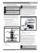
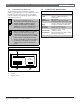
3.3.2 Safety Precautions While Handling High
Voltage
High voltage is present at the AC power
input terminals, Fuse F1, and connector J8
located in the lower right corner of the
D9142 power supply (see
Figure 3
).
Always use the dedicated circuit breaker to
remove 120 VAC before removing the covers
to the fuse or terminal block. Cover the fuse
and terminals after making connections or
testing these connections.
3.3.3 Ground the System First
Be sure to ground the system before
completing any wiring (see
Section 3.4
Connecting the Earth Ground
).
3.3.4 Safety Precautions While Handling Batteries
Wear rubber gloves and safety goggles
while connecting batteries together. Mixing
batteries of different capacities or mixing
batteries from multiple manufacturers is not
recommended.
Unplug the D9142 battery connector J7
before attaching or removing wires at the
D9142 power supply terminals.
Refer to battery manufacturer instructions
for further information about batteries and
applicable safety precautions.
Figure 3: High Voltage on D9142
1 - XFRM
2 - J8
3 - F1
4 - J5
5 - DANGER! 120 VAC
6 - Metal Oxide Varistor (MOV). Attach MOV across
HOT and GND of 110 V power input.
7 - To 120 VAC
8 - High voltage source
1 2 3
HOT NEUT GND
1
2
3
4
6
7
8
5