
Installation guide


Bosch Security Systems | 11/03 | 39352E
EN | 12
D9124 | Operation & Installation Guide |
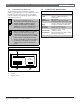
3. Installation
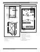
Figure 1: Enclosure
* Measurements include enclosure thickness.
1 - Back of enclosure (inside view)
Mounting holes and knockout pattern:
2 - Knockout
3 - Mounting hole
94.8 cm
(37.32 in.)
59.6 cm
(23.47 in.)
7.6 cm
(3 in.)
91.8 cm
(36.12 in.)
56.2 cm
(22.12 in.)
*91.8 cm
(36.12 in.)
71.3 cm
(28.06 in.)
60.5 cm
(23.81 in.)
0
4.9 cm1
(.93 in.)
27.9 cm
(11.00 in.)
34.1 cm
(13.48 in.)
0
3.0 cm
(1.18 in.)
7.8 cm
(3.06 in.)
14.1 cm
(5.56 in.)
42.1 cm
(16.56 in.)
48.4 cm1
(9.06 in.)
*56.2 cm
(22.12 in.)
1
2
2
3
3
2
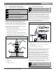
Figure 2: Mounting Locations
1 - Additional module mounting locations (use D138
mounting brackets)
2 - Control panel mounting hinge
3 - Mounting flange
4 - Module carrier mounting hinge
5 - Module carrier mounting flange
6 - Battery shelf
7 - Mounting flange
8 - Transformer mounting location
9 - Earth ground stud
*
*
*
*
*
*
*
*
*
1
6
7
6
7
8 9
5
4
3
2