
User Manual


33
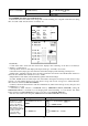
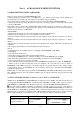
The servo sub-menu includes two features:
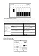
• Real-time bar-graph display to demonstrate exactly what commands the transmitter is sending to the
servos. (This can be particularly handy in setting up models with complicated mixing functions, because the
results of each stick, lever, knob, switch input and delay circuit may be immediately seen.)
• Servo cycle function to help locate servo problems prior to in-flight failures. (Channels 1-12)
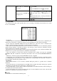
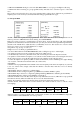
Goals
Steps
Inputs
View the result of
reassigning channel 6
from VR(A) knob to
three-position
SWITCH C
Cycle the channel 6
servo.
Complete desired programming
function.(Ex: in AUX-CH,move ch.6 to
SWITCH C)
See AUX-CH for details.
Open SERVO function
for 1s .(If ADVANCE again) .
to SERVO , PUSH
Move each control to see the
operation.(Ex: SWITCH C in all positions)
C to center position. Note change in
position of ch.6 servo.
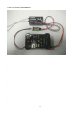
Prepare all servos to be cycled and cycle
Plug in servos. Power on.
Close
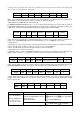
2.3.16 TELEMETARY
Signal strength and receiver voltage integrated into the radio transmitter. It is displayed as the following
configure, also it is in the sub menu RECEIVE.
Receiver voltage is shown as RX,
External voltage is shown as EXTY.