RADIOLINK AT10II (DSSS&FHSS) INSTRUCTION MANUAL RADIOLINK ELETRONIC LIMITED Technical updates and additional programming examples available at: http://www. radiolink.com.
INTRODUCTION Thank you for purchasing Radiolink 2.4 GHz 12CH remote control system -- AT10II. This system is extremely versatile, it is the most complete remote control device as so far in our product series, it can operate helicopter, fixed-wing, glider and MULTIROTOR. Radiolink, the first one who make DSSS and FHSS working synchronously come true, 16 channels pseudo random frequency hopping, QPSK modulation ensure excellent anti-interference performance, even can control stable in city center.
Note: About flying While you are getting ready to fly, if you place your transmitter on the ground, be sure that the wind won’t tip it over. If it is knocked over, the throttle stick may be accidentally moved, causing the engine to speed up. Also, damage to your transmitter may occur. Other than 2.4GHz system: Before taxiing, be sure to extend the transmitter antenna to its full length collapsed antenna will reduce your flying range and cause a loss of control.
TABLE OF CONTENTS 1 Part 1. INTRODUCTION OF AT10II SYSTEM .........................................................................5 1.1.1 1.1.2 1.1.3 1.2 1.2.1 1.2.2 1.2.3 1.3 1.3.1 1.3.2 1.3.3 1.3.4 1.3.5 2 PART 2. BASIC FUNCTION OF AIRPLANE .......................................................................... 15 2.1 2.2 2.3 2.3.1 2.3.2 2.3.3 2.3.4 2.3.5 2.3.6 2.3.7 2.3.8 2.3.9 2.3.10 2.3.11 2.3.12 2.3.13 2.3.14 2.3.15 2.3.16 3 Function of transmitter ...........................................
4 PART 4 GLIDER MODEL FUNCTIONS .................................................................................. 54 4.1 4.2 4.3 4.3.1 4.3.2 4.3.3 4.3.4 4.3.5 4.3.6 4.3.7 4.3.8 4.3.9 4.3.10 4.3.11 4.3.12 4.3.13 4.3.14 5 Part. 5 HELICOPTER MODEL FUNCTIONS ......................................................................... 64 5.1 5.2 5.2.1 5.2.2 5.3 5.3.1 5.3.2 5.3.3 5.3.4 5.3.5 5.3.6 5.3.7 5.3.8 5.3.9 5.3.10 5.3.11 5.3.12 5.3.13 5.3.14 6 SET BASIC MENU OF GLID ....................................
Part 1 INTRODUCTION OF AT10II SYSTEM Note that in the text of this manual, beginning at this point, any time we are using a feature's specialized name or abbreviation as seen on the screen of the AT10II, that name, feature, or abbreviation will be exactly as seen on the radio’s screen, including capitalization and shown in a DIFFERENT TYPE STYLE for clarity.
1.1.
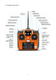
SWITCH ASSIGNMENT TABLE • The factory default functions activated by the switches and knobs for a AT10II transmitter are shown below. • Most AT10II functions may be reassigned to non-default positions quickly and easily. Always check that you have the desired switch assignment for each function during set up.
SWITCH C up = ELE-FLP on center/down= IDLE-DOWN down = AIRBRAKE on up = ELE-FLP on governor center = Distance cond. down = Landing cond. attitude SWITCH D aileron dual rate aileron dual rate aileron dual rate SWITCH E or G* Landing gear/ch5 SWITCH F or H* Snap roll /trainer —— aileron dual rate —— Throttle hold/ch5 Trainer Trainer/throttle cut trainer SWITCH G or E* —— up = Speed cond. idle-up 1 and 2 —— SWITCH H or F* —— down = Start cond.
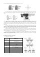
correct for minute manufacturing deviations from servo to servo. • To center the servos, connect them to receiver and turn on the transmitter and receiver. Center the trims on the transmitter, then find the arm that will be perpendicular to the pushrod when placed on the servo. • After the servos are installed, operate each servo over its full travel and check that the pushrods and servo arms don’t bind or contact each other. Also make sure the controls do not require excess force to operate.
(2)Glider/Sailplane servo connection Glider GLID (2A+1F) GLID(1A+1 F) RX output & CH ELEVON FLAPERON AILE-DIFF GLID (2A+2F) AILE-DIFF 1 Combined elev-2&aileron1 elev-1&aileron-2 Combined flap-2 &aileron-1 aileron-1 Aileron-1 2 Combined elev-1&aileron-2 Elevator/combined rudder-2&elev-1¹ Elevator/combined rudder-2&elev-1¹ Elevator/combined rudder-2&elev-1¹ 3 spare/motor spare/motor spare/motor spare/motor/splr-2¹ Rudder/combined rudder-2&elev-2² Rudder/combined rudder-2&elev-2² rudder
6 7 8 9 10 Pitch(collective pitch) Spare/governor spare/mixture control Spare spare The above listed receiver and channels is referred to the channel 1~10 of the receiver R10DS, connect the receiver with the related servo, you can control the servos by the correspondent switch.
1.2.3 Installment of antenna (1) Installment of receiver antenna 1. The antenna must be kept as straight as possible. Otherwise it will reduce the effective range. 2. Large model MULTIROTOR may of some metal part interfering signal; in this case the antennas should be placed at both sides of the model. Then the best RF signal condition is obtained at any flying attitude. 3. The antennas must be kept away from conductive materials, such as metal and carbon by at least a half inch.
5. 6. BUTTON. Turn the DIAL while still holding the END BUTTON: clockwise to brighten and counterclockwise to darken the display. User name setting: user name can be set by DIAL and PUSH with letters and numbers. Alarming voltage: Transmitter: preset 8.6V, can be self-set Receiver: preset 4.0V, can be self-set Ext: preset 10.1V, can be self-set 1.3.2 Model type Under basic menu, use CURSOR to select MODEL TYPE and enter by pressing PUSH.
TL: Shows the cumulated ON times. (Hours: minutes) T1/T2:T1/T2 timer display.(minutes: seconds) MT:Model timer display Shows the cumulated ON time for each model.(hours: minutes) Button instruction MODE BUTTON: Press and hold MODE BUTTON for one second to open programming menus. Press MODE BUTTON to switch between BASIC and ADVANCE. Press MODE BUTTON to scroll between conditions in certain functions. END BUTTON: Press END BUTTON to return to previous screen.
PART 2. BASIC FUNCTION OF AIRPLANE Please pay attention that the (BASIC) menu is suitable for all type models (airplane, helicopter, glider, multicopter). The motor cut will be introduced in Glider (Basic) Menu, except Idle down &Throttle cut. Helicopter Basic Menu include some extra function (swash plate tilting, throttle and pitch curves and the tail rotor anti torque mixing under normal flight model) will be discussed in Helicopter section. 2.
2.2 A QUICK GUIDE: GETTING STARTED WITH A BASIC 4-CHANNEL AIRPLANE This guide is intended to help you acquainted with the radio, to give you some ideas and direction on how to do. We give you a big picture overview of what we accomplish; a ‘by name’ description of what we’re doing to help you with the radio; then a step-by-step instruction to leave out the mystery when setting up your model. For additional details on each function, see that function’s section in this manual.
THR CUT shuts the engine off completely From BASIC menu, choose THR CUT with the flip of a switch.(Note: Do Not assign IDLE DOWN and THR CUT to both position of a 2 position switch Activate, assign SWITCH and adjust.
you don’t need to set every time for different plane. MODEL NAME, MODEL TYPE and transmitter voltage. Make sure that MODEL TYPE is accomplished with your plane type before flight. Or it will cause error in servo and rudder. COPY Save the present data as another model type, it will be displayed by shadow area to differ from. When this copy start, the object data will be fully covered including name, type and module type, and cannot recover.
Close Model type select •ACRO basic: Drive ACRO basic type (multi airfoil. Detail in Twin Aileron Servos, Twin Elevator Servos, ELEV-FLAP mix and V-tail) •glider: Different tail type (detail in glider type) •helicopter: 8 swash plate types (detail in helicopter type) Caution: decide a model type for the model plane. To most fixed wing plane, aero basic is better, because it has some function glider doesn’t have. While sometimes, glider (2A+1F) is better.
Goals Steps Open Basic menu, Change ATL from ON then to Mode Type. to OFF for battling robots, tanks, Go to ATL and airbrakes and other change. (Ex: to OFF) channel 3 uses. Close Inputs Mode for 1s (If ADVANCE, Mode again). To Mode TYPE, press PUSH. to ATL, to OFF. Home screen display As shown below, home screen will display plane type and throttle pitch: ILLUST: displays the illustration of helicopter in the home screen.
END POINT adjusts only the individual servo. It will have no effect on any other servo that is operated in conjunction with this servo via mix or preset programming such as FLAPERON, AILEVATOR, etc. This is so that each individual servo can be carefully fine-turn to avoid binding and other conflicts. To adjust the total travel of a function such as FLAPERON, make the adjustments in that function's controls.
any one condition will affect only that condition. Goals Steps Reset trims to neutral after having adjusted all linkage. Note: this is one of the several functions for which the radio requires confirmation to make a change Inputs Open BASIC menu, then open TRIM submenu. Double the sensitivity of the AILERONTRIM LEVERS for a first flight of an aerobatic model to ensure sufficient range to trim the model for level flight. For 1s. (If ADVANCE, again) TRIM . Confirm the reset.
you use pre-built ACRO/ GLID functions that control multiple servos, such as FLAPERON or V-TAIL, it may be confusing to tell whether the servo needs to be reversed or a setting in the function needs to be reversed. See the instructions for each specialized function for further details.
Adjustability: • Range: 0 - 140% (0 setting would deactivate the control completely.) Initial value=100% • Adjustable for each direction (ACRO/ GLID) (i.e. Up/down, left/right) (Ex: Most models fly upright without any elevator trim, but require some down elevator when inverted just to maintain level flight. By increasing the down travel by the amount required to hold the model inverted, the model now has equal travel available from level upright or level inverted.
(HELI) press the CURSOR LEVER to toggle through the 5 conditions while setting the rates. (GLID) activate the corresponding condition to edit the rates. Goals Steps Inputs for 1s.(If ADVANCE Open D/R,EXP again) to D/R EXP,PUSH. Choose channel to CH, Push. Choose first channel position to NO,PUSH. Set up dual rates Set rate and EXP(Ex: High and exponential in rate=95%,0%exponential) HELI model. Go to 2nd switch position and set rate and exponential. to Rate, PUSH.
to EXP .PUSH C to UP position confirm EXP reads 0. Set each rate’s EXP. (Ex:0%,+15%,-40%) C to DOWN position. AILERON STICK to+15% .PUSH AILERON STICK to+15%.PUSH C to center position Repeat to set low rate EXP to -40%. Repeat above steps for elevator and rudder. Close 2.3.8 Throttle Cut AEROBASIC Throttle cut (THR-CUT) (ACRO0/HELI): provides an easy way to stop the engine by flipping a switch (with THROTTLE STICK at idle).
position is NULL to avoid an accident setting on a switch to cause glitches during flight. Adjustability: • Range: -30% to +30%. Movement of servo is 0%, air brake stick is on its min and -30% on the max. • SWA-H and logic switch Ls1-3 is selectable • All position is available for logic switch including NULL (usually MIX OFF), you can set MIX by different position of a switch (UP & CEN, CEN & DN) and also NORM, REV. Goals Steps Inputs Open BASIC menu ,then open THR CUT for 1s .(If ADVANCE again) .
Goals Steps Inputs for 1s .(If ADVANCE Open BASIC menu,open IDLE DOWN again) . to IDLE DOWN,PUSH. Activate the function Decrease the throttle setting to idle with the Adjust the rate until engine flip of a switch for spins idles as desired with Throttle and landings. stick. to MIX,PUSH, to OFF Throttle Stick down, to desired rate, PUSH Optional:change switch assignment . to SW, to RATE,PUSH, to desired position, PUSH. Close *Normally a value of 10- 20%. Secure the fuselage, engine running.
Goals Change the receiver Failsafe command for channel 8(gasoline engine kill switch) to a preset position. NOTE: This is one of several functions for which the radio requires confirmation to make a change. Steps Inputs Open BASIC menu, then Open F/S. C h o o se c h a n n el to c h a n g e (E x :C H . 8 ) for 1s .(If ADVANCE again) . to F/S, PUSH to CH8 ,PUSH Set and confirm fail safe command. that controls CH8 to desired OFF position. to adjust ,PUSH Repeat as desired Close 2.3.
activated later by a throttle to CH7 MIX). Repeat above steps as desired. (Ex:CH7=NULL) to CH7,PUSH, to NUL Close 2.3.12 TIMER sub-menu (stopwatch functions): Controls three electronic clocks used to keep track of time remaining in a competition time allowed, flying time on a tank of fuel, amount of time on a battery, etc.
to 4,PUSH. Adjust time to 4min.30sec., count down to 00 TIMER<2>, PUSH to 30,PUSH to SWA TIMER<2>, to ST-THK,PUSH Throttle Stick down to 50%,PUSH for 1s to Assign switch at ST-THK and NULL. set trigger point. Throttle Stick down to desired position(Ex:1/4 stick) PUSH button for 1s to set. Close 2.3.13 TRAINER: For training novice pilots with optional trainer cord connecting 2 transmitters. The instructor has several levels of controllability.
•ALWAYS set the student transmitter modulation mode to PPM. • BE SURE that the student and instructor transmitters have identical trim settings and control motions. Verify by switching back and forth while moving the control sticks. • FULLY extend the instructor's antenna. Collapse the student's antenna. (Except 2.4GHz) • When the TRAINER function is active, the snap roll function is deactivated.
The servo sub-menu includes two features: • Real-time bar-graph display to demonstrate exactly what commands the transmitter is sending to the servos. (This can be particularly handy in setting up models with complicated mixing functions, because the results of each stick, lever, knob, switch input and delay circuit may be immediately seen.) • Servo cycle function to help locate servo problems prior to in-flight failures.
Find telemetry information: under BASIC MENU, select RECEIVE, presses PUSH to enter, you can find the telemetry info, shown as below. RX is receiver voltage, EXT is external voltage. Also temperature and engine speed (EXT, TEMPERATURE, RPM, and GPS all need telemetry sensor). RSSI is signal strength, NULL is for no signal, and 0 is for max. Connection of telemetry sensor: sensor of EXT, TEMPERATURE, RPM, GPS can connect one by one with the receiver port DATA.
Connect to telemetry module PRM-02 35
Part 3. ACRO ADVANCE MENU FUNCTIONS 3.1 AIRPLANE WING TYPES (ACRO/GLID): There are 3 basic wing types in MULTIROTOR models: • Simple. Model uses one aileron servo (or multiple servos on a Y-harness into a single receiver channel) and has a tail. This is the default setup and requires no specialized wing programming. • Twin Aileron Servos. Model uses 2 aileron servos and has a tail. See TWIN AILERON SERVOS. • Tail-less models (flying wing).
channel CH6&5 Allow twin Select AILE-2 and change to aileron servos operating with a CH6&5. 5-channel receiver. Close To AILE-2. to CH6&5 There are 4 basic tail types in MULTIROTOR models: • Simple. Model uses one elevator servo and one rudder servo (or multiple servos on a Y-harness). This is the default. • Dual Elevator servos. Model uses 2 elevator servos. • Tail-less models. Model uses 2 wing servos together to create roll and pitch control. See ELEVON (ACRO/ GLID 1A+1F). • V-TAIL.
• THROTTLE-NEEDLE mixing is a curve mix (like PROG.MIX 5 to 8) for proper in-flight needle setup. • THROTTLE DELAY mixing is a pre-programmed delay mix that slows down the response of the CH3 servo. Next, we'll get an in-depth look at some pre-programmed mixes (mixes whose channels are predefined for simplicity) we’ve not covered yet, and last, look at the fully-programmable mix types. 3.3.1 Program MIX AT10II contains four separate linear programmable mixes.
• Dial as master: To directly effect one servo’s position by moving a dial, set the master as the desired dial. (Ex: create a second throttle trim on left slider.) MASTER SLAVE VR(D) LINK TRIM OFF N/A THRO SWITCH POSITION RATE OFFSET NULL ANY 5% 0 •Slave: the controlled channel. The channel is moved automatically in response to the movement of the master channel. The second channel is in a mix’s name (i.e. aileron-to-rudder). •Link: Link this programmable mix with other mixes.
when flaps move Choose master and slave channels. Already CH6 .Already CH2 up(spoilers),5%elevator movement when flaps move down. Link should be ON if mode has twin Optional: set Master as OFST or VR(A-E) to Master, PUSH, to desired choice Set LINK and TRIM as needed. to LINK, PUSH , to DWON elevator servos. Otherwise, Link remains OFF. Assign SWITCH and position. (Ex: change from E to C, Down) Optional: set switch to STK-THR to activate mix with THROTTLE STICK.
set to any channel. • PROG.MIX5 rudder-to-aileron for roll coupling compensation (GLID mixes default to aileron-to-ELEV.) • PROG.MIX6 rudder-to-aileron for roll coupling compensation (GLID mixes default to aileron-to-ELEV.) • PROG.MIX7 rudder-to-elevator for pitch coupling compensation (GLID mixes default to elevator-to-airbrake.) • PROG.MIX8 rudder-to-elevator for pitch coupling compensation (GLID mixes default to elevator-to-airbrake.) • HELI Defaults: • PROG.
ACRO GLID The FLAPERON mixing function uses one servo on each of the two ailerons, and uses them for both aileron and flap function. For flap effect, the ailerons raise/lower simultaneously. Of course, aileron function (moving in opposite directions) is also performed. Note: When changing the polarity of a rate, "change rate dir?" is displayed for a check. Please set up after pressing DIAL for 1 second and canceling an alarm display.
ELEVON. 3.3.4 FLAP-TRIM Using FLAP-TRIM to adjust FLAPERON (ACRO/GLID) ACRO GLID FLAP-TRIM assigns the primary FLAPERON control [defaults to VR(A)] to allow trimming in flight of the flap action of FLAPERON. Note: Even if FLAP-TRIM is made active with AIL-DIFF, it will not have any effect. The ONLY function that allows control of the ailerons as flaps in the AIL-DIFF configuration is AIRBRAKE.
Note: When changing the polarity of a rate in camber-flap, "change rate dir?" is displayed for a check. Please set up after pressing DIAL for 1 second and canceling an alarm display. (GLID only) • FLAP function allows you to set up 1 or 2 servos for flap action. • The separate AILE-DIFF settings for each condition can be set. (GLID only) Goals Steps Inputs Activate twin aileron servos using AILE-DIFF. Note that the function defaults to no difference in down travel vs. up travel.
elevator trim lever in flight can be set to adjust the aileron and elevator settings in your airbrake rather than adjusting the model's actual aileron and elevator trim. This allows easy adjustment for any ballooning while in flight. When the airbrake switch is moved to off the trim is again adjusting the normal elevator trim. • Channels controlled: Elevator, twin ailerons and flap may be set independently in AIRBRAKE, including set to 0 to have no effect.
ACRO GLID ELEV-FLAP mixing is the first pre-programmed mix we'll cover. This mix makes the flaps drop or rise whenever ELEVATOR STICK is moved. It is most commonly used to make tighter pylon turns or squarer corners in maneuvers. In most cases, the flaps droop (are lowered) when up elevator is commanded. Adjustability: • Rate: -100% (full up flap) to +100% (full down flap), with a default of +50% (one-half of the flap range is achieved when the ELEVATOR STICK is pulled to provide full up elevator.
separate aileron control use ELEVON. V-shaped tail models use V-TAIL, ADVANTAGE: •Ability to adjust each servo's center and end points for perfectly matched travel. • Ease of assembly, not requiring torque rods for a single servo to drive 2 surfaces. • Elevators acting also as ailerons for extreme stunt flying or more realistic jet flying (optional). • Redundancy, for example in case of a servo failure or mid-air collision. ADJUSTABILITY: • CH2 and CH8 only.
models snap without aileron; others snap on elevator alone. Most models snap most precisely with a combination of all 3 surfaces. Additionally, rate of speed and acceleration when using the snap switch will affect how the model snaps. For information using gyros with airplanes for cleaner precision maneuvers, such as snaps and spins without over rotation. ADJUSTABILITY: • Travel: Adjust the amount of elevator, aileron and rudder travel automatically applied. • Range: -120 to +120 on all 3 channels.
Close 3.3.10 V-Tail (ACRO/ GLID) V-TAIL mixing is used with v-tail MULTIROTOR so that both elevator and rudder functions are combined for the two tail surfaces. Both elevator and rudder travel can be adjusted independently on each surface. Note: NOTE: If V-TAIL is active, you cannot activate ELEVON or AILEVATOR functions. If one of these functions is active, an error message will be displayed and you must deactivate the last function prior to activating ELEVON.
to BASIC . Open ELEVON again to ADVANCE to ELEVON, Activate the function. Activate ELEVON. Adjust aileron down travel to 90% of up travel, creating aileron differential. to MIX,PUSH Optional: adjust up/down travel separately for the servos as ailerons.(Ex: down to 90%) Optional: adjust the elevator travel of each servo.(Ex: right servos elev. Travel to 98%, left to 105%.) to ACT. to AIL1.PUSH. Aileron Stick. to 90% to AIL2.PUSH. Aileron Stick. to 90% to ELE2.PUSH. to 98%. to ELE1.PUSH.
• And we recommend that you also set to off (0%) mode for safety as follows. Goals Steps Inputs to BASIC . Set up a Open GYRO-SENSE GYA gyro setting (Ex:MIX-1) Activate the function. again to ADVANCE to GYRO-SENSE, to MIX-1.PUSH Optional: change switches assignment. Ex: select E. to SW.PUSH. Adjust gyro rates as needed.(Ex: UP to NOR70%,CNTR to 0%[off], DOWN to AVC70% as starting points. to ON. to SwE to gyro rate. Push. E to CNTR, AVC70% E up. to 0%, to NOR 70%, E DOWN, to Close 3.3.
Adjustability: • Separate curves for each switch position are available. • Moving and deleting the curve point: The curve point (-STK-) can be moved to the left or right by turning the DIAL (up to 2% in front of the adjoining point) and deleted/returned by pressing the DIAL for one second alternately. Goals Steps Inputs Open THR-CURVE to BASIC . again to ADVANCE to THE-CURVE, Activate the function. Adjust the 1st point Optional: assign the switch.
is particularly popular with contest pilots who fly in a large variety of locations, needing regular engine tuning adjustments, and requiring perfect engine response at all times and in all maneuvers. Also popular to minimize flooding at idle of inverted engine installations or installations with a high tank position. Not needed for fuel injection engines, which do this automatically. ADJUSTABILITY: • Five-point curve allows adjustment of engine mixture at varied throttle settings.
PART 4 GLIDER MODEL FUNCTIONS Please note that nearly all of the BASIC menu functions are the same for airplane (ACRO setup), sailplane (GLID 1A+1F/ 2A+1F/ 2A+2F setups), and helicopter (HELI setups). The features that are identical refer back to the ACRO chapter. The glider BASIC menu includes MOTOR CUT and does not include IDLE-DOWN or THR-CUT.
throws (usually listed as high rates). Adjust the servos’ end points. (Ex: flap servo). Close the function. Choose D/R,EXP to FLAP VR(A). , VR(A). , Repeat as needed. to desired travel. to desired travel. to D/R,EXP to CH , to CH2(ELEV). A to UP position. Screen reads ELEV [UP] to D/R Set up dual/triple rates and exponential (D/R, EXP). Choose the desired control, and set the first (Ex: high) rate throws and exponential.
Before doing anything else to set up a glider or sailplane, first you must decide which MODEL TYPE best fits your MULTIROTOR. • GLID(1A+1F): The GLID (1A+1F) MODEL TYPE is intended for sailplanes with one or two aileron servos (or none), and a single flap servo (or two connected with a y-connector). This TYPE is meant to be a very simplistic version to set up a basic glider without a lot of added features. Additional flight condition is available.
Additional flight conditions are available specifically for sailplanes. These additional flight conditions contain different offset trims to make the sailplane perform certain maneuvers more easily. Aileron differential functions may be set to provide separate rates per condition selected. Prior to setting up OFFSET, you must active the conditions and assign the switches in the CONDITION/FUNCTION.
Note: The same delay amount for elevator and rudder is recommended when using V-tail function. ADJUSTABILITY: • Delay time (-DLY-) range of 0 to 100%. The delay time is 10 second at 100%. Goals Steps Open ADVANCE menu, then open START DELAY. Ex: delay time=5 second. Activate the function Set the delay time. (Ex:50% each surface) Inputs to BASIC . again to ADVANCE to START-DLY, to MIX to ELEV , to OFF or ON , to 50% to RUDD , Repeat as needed. to 50% Close 4.3.
Goals Steps Inputs to BASIC . Open the CAMBER FLAP function. Ex: Set the maximum travel of 35% of the total flap travel. again to ADVANCE to CAMBER-FLP, Adjust the up/down trim amount separately.(Ex: adjust to 35%) 。 to FLP VR (A), to 35%, VR (A), Repeat. to 35%, Or: adjust the center position of flap servo to CENTER , 。 to desired point. Close 4.3.
Close 4.3.8 BUTTERFLY (crow) mixing BUTTERFLY simultaneously moves the flaps, twin ailerons and elevator, and is usually used to make steep descents or to limit increases in airspeed in dives. Separate two BUTTERFLY settings are available. (CRI1/CRI2) ADJUSTABILITY: • Activation: Get proportional by moving the THROTTLE STICK. • Switch: Mix SWITCH is selectable. A to H: SWITCH A to H. Also LOGIC SW (Lsw1 to 3) may be assigned. NULL: always on.
is Activate the function the Adjust the travels as needed. MIX switch is selectable (Ex: Aileron each 75%, Flap 75%) Elevator setting adjustable in B.FLY-ELE. SWA to UP position to MIX , to AIL1 , to FLP , to AIL2 , to OFF to 75%, to75%, to 75%, Close 4.3.9 AILE/ RUDD MIX You can select a pre-programmed mix which is used to mix the rudders with aileron operation or the ailerons with rudder operation. Aileron-to-rudder mix (AILERUDD): automatically creates a "coordinated turn".
about 50% is often used. For slope racing or F3B models in speed runs, you may wish to use a larger value approaching 100%. ADJUSTABILITY: • RATE range of -100 to +100. Negative setting would result in opposite aileron action from flaps. • SWITCH A-H fully assignable. Also LOGIC SW (Lsw1 to 3) may be assigned. • POSITION fully assignable, including NULL (mix always on) and Up&Cntr and Cntr&Dn to activate the mix in 2 separate positions of the same SWITCH.
Adjust the spoiler Activate the function. servo position to 60% Assign the SPO2-CH.(Ex: CH3) to MIX , to –SPO2- CH Adjust the spoiler servo position. (Ex: SPO1/SPO2=+55% to +60%) to ON. , to CH3, to –SPO1-POSI to -50%, , to 60%, to –SPO2-POSI to +50%, , to 60%, Optional: Set the elevator rate.(Ex:10%) to –rate- ELEV , to 10%, Optional: set the delay. (Ex:25%) to –dly- ELEV , to 25%, Close 4.3.13 FLAP-TRIM (see GLID 3.3.4) 4.3.
Part. 5 HELICOPTER MODEL FUNCTIONS Please note that nearly all of the BASIC menu functions are the same for airplane (ACRO setup), sailplane (GLID setups), and helicopter (HELI) setups. The features that are identical refer back to the ACRO chapter. 5.
Goals Reverse servos as needed for proper control operation. Ex: Left Rudder Stick results in leading edges of tail rotor blades moving left. Reverse to operate properly. Steps Inputs In BASIC menu, open Reverse. Choose desired servo and reverse its direction of travel. Ex: reverse rudder servo. In BASIC menu, choose END POINT. Adjust travels as needed to match model’s recommended throws.(usually listed as high rates. for 1s to BASIC.(If ADVANCE again) .
Confirm gyro direction. Goals Learn how to operate HOVERING PITCH and HOVERING THROTTLE With radio on, move helicopter’s tail to the right by hand. The gyro should give right rudder input (leading edge of the tail rotor blades move left). If the gyro gives the opposite input, reverse direction on the gyro unit itself. Steps Inputs Notice at half throttle, the VR(B) dial adjusts the throttle separately from the pitch. VR(A) adjusts the pitch separately from the throttle. for 1s to BASIC.
5.2.1 Swash Plate Types Goals Change the model type and swashplate of model#3 from MULTIROTOR to 120 degree CCPM with 2 servos working in unison for collective pitch and aileron (Ex: HELI HR3) Steps Confirm you are using the proper model memory(Ex:3) Open PARAMETER, go to MODEL SEL. Select proper MODEL TYPE (HELICOPTER) Confirm Change to desired SWASH TYPE (Ex: HR3) Confirm. Inputs On home screen, check model name and # on top left. If it is not the correct model (Ex:3) see MODEL SEL. for 1s to BASIC.
Except SWASH PLATE, function menu of helicopter is same as GLID/ ACRO. Please find the former instructions. Swash plate function rate settings (SWASH AFR) reduce/increase/reverse the rate (travel) of the aileron, elevator (except H-2) and collective pitch functions, adjusting or reversing the motion of all servos involved in that function, only when using that function.
load on the engine. Curves are separately adjustable for normal, idle-up 1, idle-up 2, and idle-up 3. In addition, a separate collective pitch curve is available for throttle hold. Sample curves are displayed in the appropriate setup types (ex: normal flight condition) for clarity. Suggested defaults: • Normal: Collective pitch curve that results in points 1, 4 and 7 providing .4, +5, (+8 to +10)* degrees pitch. A throttle curve setting of 0, 25, 36, 50, 62.5, 75, 100%.
direction when collective pitch is increased; for counterclockwise-turning, the opposite. Change the operating direction setting by changing the signs of the numbers in the curve from plus (+) to minus (-) and vice versa. Suggested defaults: Clockwise rotation: -20, -10, 0, +10, +20% from low throttle to high. Counterclockwise rotation: +20, +10, 0, -10, -20% from low throttle to high. Adjust to the actual values that work best for your model. Revo.
Hover point: Adjust collective pitch curve to +5 degrees. Ease heli into a hover. Land/shut engine o f f . A d j u s t t hrottle curves and rudder trim. Repeat until model hovers smoothly at half throttle. Rapidly apply throttle from 1/4 to 1/2 stick. Adjust REVO. points 2 and 3 until the model does not rotate its nose up on throttle application. Adjust THR-CURV/NOR Repeat above as needed Adjust PIT-CURV/NOR Repeat above as needed Adjust REVO.
setting in idle- up3 Adjust gyro rates as needed. to NORM, and normal. (Ex: NORM, IDL3 to NOR 50%. IDL1 and 2 to AVC 50% as starting to IDL1 points.) Repeat. , , to NOR 50% to AVC 50% Close 5.3.4 THROTTLE HOLD This function holds the engine in the idling position and disengages it from the THROTTLE STICK when SWITCH AT10II is moved. It is commonly used to practice auto-rotation.
ADJUSTABILITY: • Rotor speed changes caused by temp., humidity, altitude or other changes in flying conditions are easily accommodated. • Both adjustments may be inhibited if not desired. • Both adjustments may also be set to NULL, temporarily turning off the knob but maintaining the last memorized setting. • Adjustments may be memorized and then the knobs returned to center point to use that amount of adjustment, allows easy use of the trimming knobs for multiple models.
• You may define high and low side rate trim knobs (the high side pitch trim control is defined as the right side lever at initial setting). • The conditions are activated in the CONDITION SELECT function. • Both adjustments may be set to MANUAL, temporarily turning off the knob. • Adjustments may be memorized and then return the knobs to center point to use that amount of adjustment, allows easy use of the trimming knobs for multiple models.
Goals Steps Inputs to BASIC menu, Open the OFFSET function. again to ADVANCE menu to OFFSET. Set up separate Activate the function. trims for each of the three idle-up Change switch setting to Cond. conditions. Adjust the idle-up Select IDL2. 2 rudder trim to correct for torque at Adjust trim settings as needed. (Ex:rudder to +8%.) high speeds. to MIX , to ON. to SW , to Cond, to NO. , to RUDD Close menus and confirm slowed transitions. to IDL2, , to +8%, E (AT10II) from NORMAL to IDL2.
5.3.9 GOVERNORS: The Governor mixing function is used to adjust the Governor speed settings (rS1, rS2, rS3) from the transmitter. What is a governor? A governor is made up of a set of sensors which read the RPM of the helicopter’s head, and a control unit that automatically adjusts the throttle setting to maintain a constant head speed regardless of changes in pitch of blades, weather conditions, etc. Governors are extremely popular in competition helicopters due to the consistency provided.
additional channel and a programmable mix. The GV-1 controls throttle when it is active, so the throttle will not obey any Failsafe settings preset for throttle in the transmitter. Always set the Failsafe setting for the GV-1's on/off channel to OFF. This way the governor is shut off and the throttle obeys the Failsafe throttle commands. Goals Steps Inputs Open and activate the GOVERNOR Function. Activate the function. to BASIC menu, ADVANCE again to to GOVERNOR , to MIX to ACT.
Repeat as needed. Close 5.3.11 SWASH-RING This function is to limit movement of swash plate to avoid damage to the SWASH ROB during operation aileron and ELEVATOR. It is affected in 3D flight. Movement of AILERON and ELEV is limited in the circle. ADJUSTABILITY: • Initial: 100% • adjusting range: 0-200% Goals Steps Inputs Open SWASH-RING To prevent damaging the swash linkage by simultaneous operation of function. the ailerons and elevators, set the limit point where swash throw stops.
ADJUSTABILITY: • SWITCH G (AT10II) or E (AT10II) is programmed for normal (NORM), idle-up 1 (IDLE-UP1), and idle-up 2 (IDLE-UP2) curves, adjustable in CONDITION SELECT (IDLE-UP1/2, IDLE-UP3 items). (IDLE-UP1/2 3-position type switch only, IDL3 2-position type switch only) • Activated with the throttle curve for that condition in THR-CURVE. • Curves are adjusted to maintain constant RPM even when the collective pitch is negative (inverted).
Part 6. MULTIROTOR FUNCTIONS MULTIROTOR menu is the most differ between AT10II and AT10. The menu makes it easier to fly multirotor. The basic function menu is same like ACRO, GLID and HELI, please find the detail in the former chapters. Now let’s start the basic setting, take a quad copter for example: Goals Prepare your MULTIROTOR. Steps Inputs Install all servos switched, receivers, etc. per your model’s instructions.
to CH , to CH:2 (ELEV) SwA screen reads ELEV (UP) Set up dual/triple rates and exponential (D/P, EXP) (Note that in the middle of the left side of the screen is the name of the channel and the switch position you are adjusting. Two or even THREE rates may be set per channel by simply choosing the desired switch and programming percentages with the switch in each of its 2 or 3 positions.
Goals Steps Inputs Turn on the transmitter, Open BASIC menu, find MODEL TYPE. menu (If ADVANCE, for 1 sec. to BASIC again) to MODEL TYPE Select proper MODEL TYPE. (Ex: MULTIROTOR) Go to MODEL TYPE Choose proper model type (Ex: MULTIROTOR). Confirm the change. to TYPE for 1 sec. ‘Are you sure?’ to MULTIROTOR, Displays, to confirm. to AILE-TR , to ON. Repeat above to turn on other trims Turn on the trim. Close 6.1.
AT10II Using Tutorials RadioLink AT10 + R10D Binding https://www.youtube.com/watch?v=rhdB6KgVsMw RadioLink AT10 + PRM-01 Telemetry Module https://www.youtube.com/watch?v=uWSxWrYUwAg AT10 Firmware Upgrade https://www.youtube.com/watch?v=SU-AclRNwWY&t=47s RadioLink AT10 and NAZA in SBus https://www.youtube.com/watch?v=nxU8RnwjTs4&t=372s Mission Planner Calibration and Radiolink AT10 setup Flight Modes https://www.youtube.