
User's Manual

6 S-Series GSM/GPRS Radio Base Station
RadioFrame Networks, Inc.
2 The S1 Indicators, Connectors and Reset Button
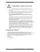
S1 LEDs are located on the front panel, shown in Figure 1, and connectors and the reset
button are located on the back panel, shown in Figure 2.
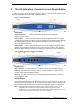
Figure 1 Front Indicators
Indicators
Connected Indicator Green. Lights when the S1 detects a valid cell
communication channel.
LAN Indicators
Green. The LAN indicators serve two purposes. When the light is
steadily ON, it indicates that the S1 router is connected to an Ethernet device through
the corresponding LAN port. When the light is flashing, the router is sending or
receiving data over that port.
WAN Indicators Green. The WAN indicator serves two purposes. When the light is
steadily ON, it indicates that the S1 router is connected to a cable or DSL modem.
When the light is flashing, the router is sending or receiving data over the WAN port.
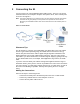
Figure 2 Back Connectors and the Reset Button
Connectors
Power Connector The power connector is where you connect the power adapter.
LAN Ports
The LAN ports connect to devices, such as computers or print servers,
using a CAT5 (or better) Ethernet cable.
WAN Port The WAN port connects to your cable or DSL modem using a CAT5 (or
better) Ethernet cable.
Reset Button
The Reset button reboots the S1 when you press it for just a second. If you press the
Reset button for 30 seconds, the S1 is reset to factory defaults. Router settings, such
as password, static IP addresses, and port forwarding table entries are all cleared.
Note: Resetting the S1 (as opposed to rebooting it) clears any settings, such as router
configuration and replaces them with the factory defaults. If you have made
modifications, it is a good idea to write down these settings before doing a Reset. You
can find most of them on the Status screen. (See Chapter 4.)