
User's Manual

Installing the RadioFrame System
13
Install the NCU
The NCU is the main controller of the RadioFrame System. Typically, the NCU is
mounted in a rack in a telecommunications room or other closet supplied with
120VAC.
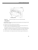
Unpack and mount the Network Chassis Unit (NCU)
1 Find these items in the NCU shipping container: one NCU, four mounting
screws, one 120VAC power cord, one coaxial cable with two male BNC
connectors, and one set of product documentation.
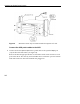
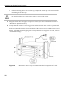
2 Mount the NCU only in an EIA-standard compliant (19”) rack using all 4 screws
provided. Refer to the SDS for the exact location of the NCU. For safe operation,
follow these guidelines:
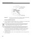
• Do not mount the NCU in any orientation other than that specified in the
following illustration.
• Mount the NCU so that both the front and the back are accessible.
• If the mounting holes do not line up, adjust the NCU up or down until the
mounting holes line up.
Caution
Do not block the air vents on the sides or rear of the NCU.
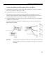
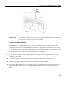
3 Plug the NCU into an approved power source (for more information, refer to
“Hardware Specifications”).
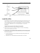
4 Verify that the NCU is receiving power and that each NCU card is operational.
Each card installed in the front and back of the NCU has two LEDs: Power and
Status. All LEDs should light green. If any LEDs do not light or are red, refer to
“Troubleshooting.”
Note!
The Status li
g
ht on the top card in the front of the NCU will remain red
until the NCU is connected to a timing source.