
User's Manual


MC-Series ©2008 RadioFrame Networks, Inc. 5-3
Proprietary and Confidential Information
MC-Series Standard Capacity system998-1019-01 Rev X1
11. Using the breaker on the PDU, turn up the RF Shelf and then verify that the RF
Shelf is operational before proceeding. The POWER and ALARM LEDs on the
front of the RF shelf will turn green.
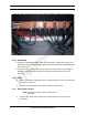
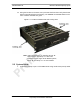
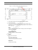
Figure 5.1 Location of DRBS Side Rail Locking Arms
Note: Image shows Group “A” installed, Group “B”
cover in place, and Group “C” with cover
removed. For the single sector MCSC system,
Group “B” and Group “C” are not installed.
5.2 System Setup
1. Connect the laptop to port 7 of the ABIC CRIC using an Ethernet (CAT-5) cable.