
User's Manual


MC-Series ©2008 RadioFrame Networks, Inc. 4-11
Proprietary and Confidential Information
MC-Series Standard Capacity system998-1019-01 Rev X1
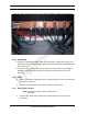
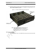
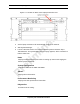
4.3.8 EAS Alarm Cabling
1. Follow procedures for routing the alarm cables through the rear of the cabinet.
2. Connect the alarm cables to the back of the EAS:
EAS: USER ALARM / CONTROL
EAS: SYSTEM ALARM / CONTROL
3. Terminate the alarm cables to the two blocks on the backboard, making sure
that each cable is connected to its specific block.
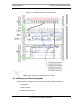
4.3.9 RF (Tx / Rx and Rx diversity)
The MCSC system cabinet provides the following RF connectors at the rear of the
enclosure for connection to the site RF distribution system:
•Tx / Rx
•Rx Div
Connect the female N-type connectors to the onsite RF distribution system
(antenna, DAS, etc.).
4.3.10 Power
1. Connect the powerplant to the PDU using two (2) -hole terminal lugs. Type is
Panduit 2-hole, P/N LCD6-14A, or equivalent. Crimp tool needed: CT-1700.
Important:
RadioFrame Networks recommends placing a 20 A breaker between the
customer power supply and the MCSC system equipment.
Warning
Verify that all breakers in the PDU are in the OFF position prior to proceeding.
Leave them in the OFF position until instructed otherwise.