
User's Manual


MC-Series Standard Capacity system
998-1019-01 Rev X1
4-10 ©2008 RadioFrame Networks, Inc. MC-Series
Proprietary and Confidential Information
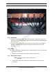
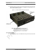
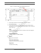
Figure 4.6 Top of Rack (TOR) Rear of the cabinet, Bulkhead, Cabling and Equipment
4.3.5 Grounding
1 Ground the cabinet ground bar to the site according to instructions using 2-hole
terminal lug. Type is Panduit 2-hole, P/N LCD6-14A, or equivalent. Required crimp
tool is CT-1700.
2 Connect the site ground to the ground at the rear of the enclosure according to
installation procedures (see Figure 4.6 for ground location at the rear of the
enclosure).
4.3.6 T1/E1
1. Follow procedure for routing the site T1 cable through the rear of the enclosure
as shown in Figure 4.6.
2. Connect the T1/E1 cable to the CSU according to instructions.
4.3.7 GPS Surge Arrestor
Note: The Surge Arrestor comes installed in the
enclosure.
1. Connect each GPS surge arrestor to the GPS antenna coax according to
procedures.