
User's Manual


MC-Series Standard Capacity system
998-1019-01 Rev X1
4-8 ©2008 RadioFrame Networks, Inc. MC-Series
Proprietary and Confidential Information
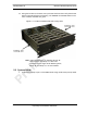
4.3 Cabinet-to-Site Cabling
Follow the for installing the following wiring at the site, and then complete the
procedures in this section to complete the cabinet-to-site cabling. See Table 4.1 for
rear of the enclosure connections.
• Grounding
• T1/E1
• GPS surge arrestors (pre-installed)
• Surge arrestors for Tx/Rx/RX Div (pre-installed(
• EAS alarm cabling
• RF (Tx / Rx and Rx diversity)
• Power
• Air Conditioning (Power)
4.3.1 Matching Terminals for PDU and Ground
Select from the list of termination lugs in Table 4.1 (listed is the smallest
packaging size available); use two when connecting the powerplant to the PDU
and one when connecting the PDU ground to the top of the bus bar. Ground lug is
included.
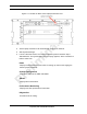
Table 4.1 Power Lugs
Note: Crimp Tool needed: CT-1700
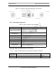
4.3.2 GPS surge arrestor
Table 4.2 shows the surge arrestor dimensions and performance specifications.
P/N AWG Config. Quantity (per Package)
LCD2-14A-Q 2 Straight 25
LCD2-14AF-Q 6 Straight 25
LCD6-14A-L 2 Right Angle 50
LCD6-14AF-L 6 Right Angle 50