
User's Manual

MC-Series Standard Capacity system
998-1019-01 Rev X1
4-6 ©2008 RadioFrame Networks, Inc. MC-Series
Proprietary and Confidential Information
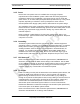
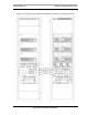
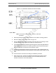
Figure 4.3 Connection between EAS Control Port and PDU Status Connectors
Note: Figure 4.3 does not show all cabling.
4.1.3 CSU
Note: If you need to install an CSU, follow this
procedure:
1. Remove the cabinet mounting rails from the CSU mounting location.
2. While supporting the CSU, slide the CSU into the cabinet mounting position.
3. Mount the CSU in the location shown in the Figure 4.1. As necessary, follow the
equipment manufacturer's installation procedure for mounting the CSU.
4. Connect the RadioFrame Networks-provided ground cable (P/N 820-0609-10;
CSU to GND BAR) between the cabinet ground bar and the grounding lug on
the rear of the CSU, and ensure the connection is tight.
5. Connect the RadioFrame Networks-provided power cable (P/N 820-0615-50;
CSU to PDU-CSU) to the CSU power.
6. Connect the other end of the power cable to the circuit breaker on the PDU.
7. Connect the CSU to the iSCIII according to procedure.
8. Using a CAT-5 cable, connect 10/100 Ethernet port 1 on the CSU to port 8 on
the ABIC ERTM for remote-management access.
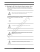
Warning!
Always connect the power cable to the CSU before connecting the power cable to
the PDU.