
User's Manual

MC-Series ©2008 RadioFrame Networks, Inc. 3-5
Proprietary and Confidential Information
MC-Series Standard Capacity system998-1019-01 Rev X1
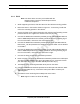
3.2.5 Power
Ensure that a DC power source is available that can supply full power
requirements for both the MCSC system cabinet and all ancillary equipment
(including a heater) for the installation. This power source may be a bulk DC
power source, or an external DC powerplant. Backup batteries may or may not be
required, depending on whether or not the powerplant is driven from an
Uninterruptible Power Supply (UPS). Refer to standards for DC power design.
Any installation of AC power conductors shall be done by a licensed, bonded and
insured electrician. Follow standard design practices for AC and DC power circuits
including any required AC surge protection. Identify any contract labor and
materials required.
Refer to Chapter 2 (Specifications) for DC power requirements. Plan to use
termination lugs. Type is Panduit 2-hole, P/N LCD6-14A, or equivalent. Required
crimp tool is CT-1700.
3.2.6 Grounding
The MCSC system cabinet must be grounded to either a defined equipment
grounding system in a facility or to the building grounding electrode in a customer
facility. Plan to install a grounding system for the MCSC system cabinet and
ancillary hardware. Refer to Chapter 7 and Appendix C of Motorola R56, as
modified , for grounding standards. The Master Ground Bar (MGB) will be
installed on the wall on the telco board. Plan to use termination lugs. Type is
Panduit 2-hole, P/N LCD6-14A, or equivalent. Required crimp tool is CT-1700.
3.2.7 GPS Antennas
Refer to the Motorola Gen 3 Site Controller System Manual, 68P80801E30-O
document and standards for GPS antenna design and installation. Per the NEC
(1) any cabling run through an air plenum shall be plenum-rated, and (2) cabling is
not to be laid on or suspended from any ceiling grid or attached to the grid
supports. Identify any contract labor and materials required.
3.2.8 T1 Service
Install T1 cabling from the point of demarcation to the MCSC system cabinet, and
provide UL497B surge protection for the T1 circuit involved. Use standard -
approved surge arrestors for the T1 circuit. Per the NEC (1) any cabling run
through an air plenum shall be plenum-rated, and (2) cabling is not to be laid on or
suspended from any ceiling grid or attached to the grid supports. Identify any
contract labor and materials required to extend the T1 service from the
demarcation point to the MCSC system cabinet. For ease of maintenance,
RadioFrame Networks recommends locating the demarcation point (SmartJack)
in the same space as the MCSC system cabinet.
Refer to the Motorola Gen 3 Site Controller System Manual, 68P80801E30-O
document and standards for T1 design and installation.