
User's Manual


MC-Series ©2008 RadioFrame Networks, Inc. 2-5
Proprietary and Confidential Information
MC-Series Standard Capacity system998-1019-01 Rev X1
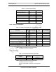
2.4.1 Receiver Performance Summary
Table 2.8 Receiver Performance Summary
Note: 1: Unless otherwise stated, all values are
referenced to the rear of the enclosure.
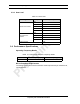
2.4.2 Transmitter Performance Summary
Table 2.9 Transmitter Performance Summary
Note: 1: Unless otherwise stated, all values are
referenced to the rear of the enclosure.
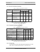
2.4.3 Tx Power Out
The transmit power out at the Top of Rack (TOR) is dependent on the OMC
datafill. Table 2.10 displays defaultTxPower vs. TOR output Power.
Parameter Condition (NOTE 1)
Value
Unit
Min Typ Max
Rx Input Level
2% BER
–106 -- –40 dBm
Absolute Maximum where
no damage occurs
-- -- +10 dBm
Residual BER
Input signal level of –80
dBm
-- -- 0.1 %
RSSI
Input signed level -80dBm at
ambient operating
tempateure of 25°C
-3 +3 dB
BER in the presence
of the adjacent
channel interferes
input signal level of 100
dBm and interfere signal
level f -60 dBM
2%
Parameter Condition (Note 1)
Value
Unit
Min Typ Max
Tx Output Power Level
OMC Datafill: Default
TxPower = 9.8
+31 +33 +34 dBm
Tx Output Power Control Range
+22 -- +36 dBm
Transmit port VSWR
Referenced to a 50
impedance
10 -- dB
Downlink Signal Quality Estimator
(SQE)
Average value
-- 30 -- dB
Occupied bandwidth Per carrier
-- -- 18.5 kHz
RF Frequency Tolerance (Tx) Average frequency
-- -- ± 50 Hz