
User's Manual


MC-Series Standard Capacity system
998-1019-01 Rev X1
1-24 ©2008 RadioFrame Networks, Inc. MC-Series
Proprietary and Confidential Information
• Plan to provide conduit or other wire routing from a door sensor, HVAC units
(if separate HVAC units are installed for the installation), and AC power
failure / surge arrestor failure sensors.
For more information about the EAS, refer to the Motorola document Gen 3 Site
Controller System Manual, 68P80801E30-O.
For more information regarding the Alarm wiring, refer to Appendix C , Section
C.1.10 (Alarm Cabling).
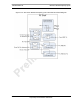
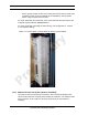
Figure 1.17 Punch Block Location within the MCSC system cabinet
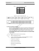
1.8.3 Channel Service Unit (CSU--(must be installed))
The Channel Service Unit (CSU) provides the T1/E1 connection between the
iSCIII and the telephone company that provides the T1/E1 line. The CSU provides
surge protection to the T1/E1 line and loop-back testing for the telephone
company.