
User's Manual

MC-Series Standard Capacity system
998-1019-01 Rev X1
1-18 ©2008 RadioFrame Networks, Inc. MC-Series
Proprietary and Confidential Information
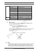
2. The largest group of carriers which fall within the 1.25 MHz band is
assigned to the MCRB if one is available. (Note: This process repeats
until there are no remaining unassigned MCRBs.)
3. Any carriers that remain unassigned, an alarm is sent to the OMC.
4. If any MCRBs are unassigned, they become standby blades.
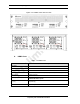
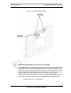
1.6.8 MC-Series Standard Capacity RF Shelf
The MCSC system provides one RF shelf per sector. The RF shelf contains
amplifiers, filters, combiners, redundant DC-DC converters and fans to provide
cooling to the power amplifiers (PAs).
The transmit chain includes a software-controlled variable attenuator for adjusting
the Tx power output at the rear of the enclosure, a multi-channel linear power
amplifier (PA), a band pass filter and a sampling port. The Tx sampling port
provides approximately Top of Rack (TOR) minus 20 dB output power. The Tx
power output at the rear of the enclosure can be varied by changing the datafill.
The PA is sized to allow sufficient linearity and gain such that a minimum of+36
dBm per carrier for up to 3 carriers, +33 dBm per carrier for up to 6 carriers and
+30 dBm for 12 carriers can be achieved at the rear of the enclosure. The
sampling port signal is brought out to the front of the RF shelf to provide
monitoring and testing of the transmit path.
The receive path contains a band pass filter, low noise amplifier (LNA) and a
sampling port. As with the Tx sampling port, the Rx sampling port is brought out to
the front panel of the RF shelf. The Rx sampling port provides approximately Top
of Rack (TOR) minus 20 dB output power.
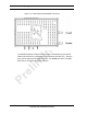
Input/Output is directed through the following ports:
•Tx/Rx
•Rx Div