
User's Manual

MC-Series ©2008 RadioFrame Networks, Inc. 1-15
Proprietary and Confidential Information
MC-Series Standard Capacity system998-1019-01 Rev X1
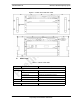
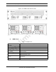
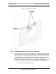
B. DRBS Indicators
The front of the DRBS has the following LED indicators:
•
STATUS indicator for each group
•
RADIOBLADE TRANSCEIVER STATUS indicators, one for each
RadioBlade transceiver slot in the DRBS. LEDs are arranged by group (8
per group) and are numbered consecutively from left to right:
• A: 1-4/1D-4D
• B: 5-8/5D-8D
• C: 9-12/9D-12D
Each RJ-45 port (rear only) has an Ethernet
link LED that indicates
connectivity and an Ethernet
activity LED that indicates Ethernet traffic.
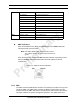
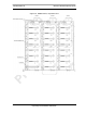
Table 1.5 DRBS Indicator LEDs
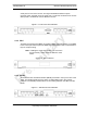
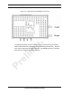
1.6.7 Multi-Channel RadioBlade (MCRB) Transceivers
Each multi-channel RadioBlade (MCRB) transceiver corresponds to up to six
iDEN carriers in the 800E MHz band.Refer to Figure 1.11.
This edge connector provides all data interfaces and clock inputs to the
RadioBlade transceiver. The RF interface employs two SMA connectors, one for
transmit and the other for receive.
LED Indication
STATUS Indicates timing synchronization for group
RADIOBLADE TRANSCEIVER STATUS
Indicates status of RadioBlade: green = operational;
red = alarm condition; not lit = RadioBlade not present