
User's Manual

MC-Series Standard Capacity system
998-1019-01 Rev X1
1-14 ©2008 RadioFrame Networks, Inc. MC-Series
Proprietary and Confidential Information
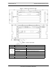
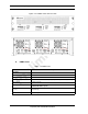
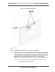
Figure 1.10 DRBS Front and rear View
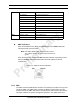
A. DRBS Ports
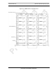
Table 1.4 DRBS Ports
Ports Description
Front Ports
Service Access (A, B, C) technician local serial access
Rear Ports
Tx / Rx (A, B, C) Input and output for RF Shelf (wiring depends on system configuration)
Fan (A, B, C) Power connector
Alarm Input (A, B, C)
ALARM serial port on the back of RF Shelf; THESE PORTS ARE NOT
USED WITH MCSC system
10/100 RadioFrame Networks
(A, B, C)
100Base-T Ethernet from ABIC ERTM Ethernet ports 1, 2 and 3
(respectively)
Ref Clock not currently used