
User's Manual

MC-Series Standard Capacity system
998-1019-01 Rev X1
1-10 ©2008 RadioFrame Networks, Inc. MC-Series
Proprietary and Confidential Information
B. ABIC Indicators
Each card installed in the ABIC has a Power LED and a Status LED that
indicates timing synchronization.
Note: The CRIC Status LED represents PLL status.
The system will not go active unless this LED is
green.
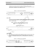
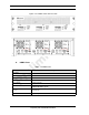
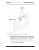
Each RJ-45 port has an Ethernet link LED that indicates connectivity and an
Ethernet activity LED that indicates Ethernet traffic (ABIC RJ-45 Port
Indicators10).
Figure 1.4 ABIC RJ-45 Port Indicators
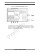
1.6.2 CRIC
The ABIC Common RadioFrame Interface Card (CRIC) is located in the top front
slot of the ABIC. The ABIC CRIC provides the Ethernet switch fabric to route
packets to/from the ABIC and hosts a microprocessor that serves as the primary
controller of BPCs for system-management purposes. The ABIC CRIC has a
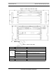
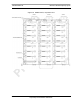
ERTM
Port 2 (RJ-45) CRTC Port 10BaseT
Port 3 (RJ-45) RF Shelf 1 10/100 Port 1
Port 4 (RJ-45) RF Shelf 2 10/100 Port 1
Port 5 (RJ-45) RF Shelf 3 10/100 Port 1
Port 6 (RJ-45) Group A
Port 7 (RJ-45) Group B
Port 8 (RJ-45) Group C
5 MHz/1PPS IN iSCIII 5-MHz/1PPS port
5 MHz/1PPS OUT not currently used (no terminator required)
GPS ANT not currently used
CRTC
10Base2 – iSCIII iSCIII 10Base2 port
10BaseT – iSCIII ABIC ERTM port 1
link activit
y