
User's Manual


MC-Series ©2008 RadioFrame Networks, Inc. 1-5
Proprietary and Confidential Information
MC-Series Standard Capacity system998-1019-01 Rev X1
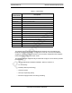
Table 1.1 FRU Table
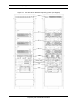
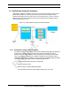
The MCSC system contains both RadioFrame Networks and non-RadioFrame
Networks equipment enclosed in a single 30” H x 25” W x 30” D Air Conditioned
equipment cabinet. The MCSC system is a three-sector configuration that supplies
twelve RadioBlade transceivers per sector.
The MCSC system is shipped ready to install and configure. The customer provides
the following:
• All non-RadioFrame Networks hardware. Refer to Section 1.8
• T1 connectivity
• Datafill (network provisioning)
• Antenna system
• GPS (as required by iSCIII)
• Electrical supply and the necessary permitting
RadioFrame
Networks PN
Description
176-0610-XX Power Distribution Unit (PDU)
176-1040-XX Airlink/BTS Interface Chassis (ABIC)
176-7090-XX MC-Series system Rx Filter
176-1076-XX MC-Series system RF Shelf
176-1030-XX Diversity RadioBlade Transceiver Shelf (DRBS) (3)
176-1090-XX 800E Tx Filter
176-1223-01 Outdoor Pole Mount Enclosure
176-1219-XX Fan Tray (w/fans) for a 4u Chassis
176-0011-XX Fans for DRBS and RF Shelf
176-7555-XX Base Processing Card (BPC) w/(2) SPAM-HC
176-7540-XX MC Common RadioFrame Interface Card (CRIC)
176-7562-XX Ethernet Rear Transition Module (ERTM)
176-0820-CC Coaxial RMII Transceiver Card (CRTC)
176-7502-XX 4U Chassis
176-0860-XX MCRB iDEN FRU