
User's Manual


MC-Series Standard Capacity system
998-1019-01 Rev X1
9-24 ©2008 RadioFrame Networks, Inc. MC-Series
Proprietary and Confidential Information
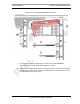
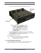
Figure 9.13 RF Shelf Showing Side-Rail Locking Arm Locations
Note: This image shows the default Main enclosure,
single sector configuration with the Group “A”
RadioBlade transceivers installed, Group “B”
location (RadioBlade transceivers not installed)
with the cover plate in place, and Group “C”
(RadioBlade transceivers not installed) with the
cover plate removed.
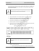
7. In System Manager, refresh the DRBS Status page until the RadioBlade
transceiver icon status bar changes from red (not present) to yellow (present
and locked). This will take approximately three minutes.
8. Unlock the RadioBlade transceiver.
Note: On the RadioBlade Transceiver Control page, the
State of the RadioBlade transceiver will change
from 2 (locked) to 11 (unlocked).
9.8 Power Distribution Unit (PDU)
The Power Distribution Unit (PDU) receives DC input and supplies power via
dedicated circuit breakers to each component in the MCSC system.