
User's Manual

MC-Series ©2008 RadioFrame Networks, Inc. 9-9
Proprietary and Confidential Information
MC-Series Standard Capacity system998-1019-01 Rev X1
2. Disconnect cabling from the back of the chassis to be replaced.
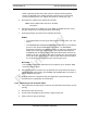
Table 9.3 For the ABIC, disconnect the cabling (from the rear of the ABIC only) listed in Table
9.3.Cables to be Disconnected from the ABIC )
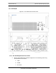
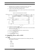
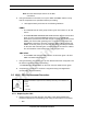
3. Remove the four front mounting screws from the front of the unit (see Figure
9.4).
4. Remove the chassis from the cabinet, and package it for shipment.
Figure 9.4 Front View of ABIC Showing Screw Locations
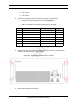
5. Mount the replacement chassis.
a. While supporting the chassis, slide the chassis into the cabinet
mounting position.
b. Secure the chassis to the cabinet mounting rails using the four mounting
screws provided with the unit.
c. Tighten the screws to 4.5 Nm (40 in-lb).
Index Disconnect From To Type
D ABIC: power PDU: ABIC power
A ABIC: ground GND BAR ground
I-1 ABIC: ERTM PORT 1 ABIC: CRTC 10baseT - ISC UTP
I-2 ABIC: ERTM PORT 2 ABIC: ERTM PORT 4 UTP
B ABIC: CRTC 10base2 - ISC ISC: 10B2-1 COAX (See Note)
C ABIC: CRTC 10baseT - ISC ABIC: ERTM PORT 1 UTP (See Note)
H ABIC: ERTM 5MHz/1PPS IN ISC: SITE REF OUT 1 COAX