
User's Manual

MC-Series Outdoor Pole Mount Users Guide998-5005-01 Rev X1
MC-Series ©2007 RadioFrame Networks, Inc. 6-9
CONFIDENTIAL AND PROPRIETARY
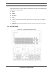
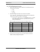
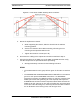
Figure 6.4 Front View of ABIC Showing Screw Locations
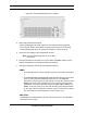
5. Mount the replacement chassis.
a. While supporting the chassis, slide the chassis into the Cabinet
mounting position.
b. Secure the chassis to the Cabinet mounting rails using the four
mounting screws provided with the unit.
c. Tighten the screws to 4.5 Nm (40 in-lb).
6. Reconnect the cabling to the replacement chassis as defined in Step 2 .
7. Using the breakers on the PDU, turn up the ABIC and DRBS and then verify
that the components are operational before proceeding.
a. Wait approximately 3 minutes for the following indicators:
DRBS:
• The STATUS LED for each group will turn green in this order: A and then
C.
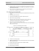
• The RADIOBLADE TRANSCEIVER STATUS LEDs will turn red and then
green for each present RadioBlade transceiver. If no RadioBlade
transceiver is present, the LED will not light. To verify the contents of the
DRBS, pull out the shelf (powering off is not required) and inspect the
RadioBlade transceivers and their respective status LEDs. Reinsert the
DRBS. To do this, press up on one side rail locking arm and press down
on the other side rail locking arm, and then push the unit into the Cabinet.
For an illustration of the locking arms, refer to Figure 6.13.