
User's Manual

MC-Series Outdoor Pole Mount Users Guide
998-5005-01 Rev X1
6-8 ©2007 RadioFrame Networks, Inc. MC-Series
CONFIDENTIAL AND PROPRIETARY
6.4 Replacing a Chassis: ABIC or DRBS
6.4.1 ABIC
1. Power down RadioFrame Networks equipment in the following order using
circuit breakers on the PDU:
• ABIC
• DRBS
• RF Shelf
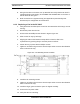
2. Disconnect cabling from the back of the chassis to be replaced. Refer to
Appendix C (OPM iDEN Microcell Cabinet Stack-Up Configuration).
a. For the ABIC, disconnect the cabling (from the rear of the ABIC only)
listed in Table 6.3. (Table 6.3 is indexed to the cabling figures in
Appendix C (OPM iDEN Microcell Cabinet Stack-Up Configuration).)
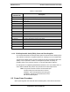
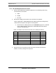
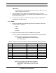
Table 6.3 Cables to be Disconnected from the ABIC (shown grayed out)
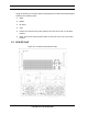
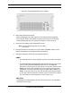
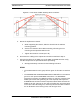
3. Remove the 4 front mounting screws from the front of the unit (see Figure 6.4).
4. Remove the chassis from the Cabinet, and package it for shipment.
Index Disconnect From To Type
D ABIC: power
PDU: ABIC
power
A ABIC: ground
GND BAR
ground
I-1 ABIC: ERTM PORT 1 ABIC: CRTC 10baseT - ISC UTP
I-2 ABIC: ERTM PORT 2
ABIC: ERTM PORT 4
UTP
B ABIC: CRTC 10base2 - ISC
ISC: 10B2-1
COAX (See Note)
C ABIC: CRTC 10baseT - ISC
ABIC: ERTM PORT 1
UTP (See Note)
H ABIC: ERTM 5MHz/1PPS IN
ISC: SITE REF OUT 1
COAX