
User's Manual

MC-Series Outdoor Pole Mount Users Guide998-5005-01 Rev X1
MC-Series ©2007 RadioFrame Networks, Inc. 6-7
CONFIDENTIAL AND PROPRIETARY
8. Using the breaker on the PDU, turn up RF Shelf and verify that the RF shelf is
operational before proceeding. The POWER and ALARM LEDs on the front of
the RF Shelf will turn green.
9. Refer to sections 2.2 (System Setup) and Appendix D (Functionality Test
Procedures) for configuration and verification.
6.3.2 Replacing a Fan in the RF Shelf
1. Verify which fan has failed (look at each fan and determine which fan(s) are not
turning).
2. Disconnect power from the fan.
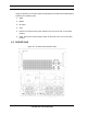
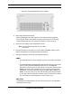
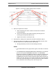
3. Unscrew the two Phillips screws shown in Figure Figure 6.3.
4. Slide out the fan tray by its flange.
5. Aligning the tabs on the bottom and top with the chassis, slide in the
replacement tray pushing firmly to seat the power connector.
6. Fasten the tray in place with the Phillips screws.
7. Tighten to 10 in/lbs using a hand or electric torque driver to ensure that vibration
does not loosen the tray.
Figure 6.3 Fan Mounting Screw Locations
8. Install the fan mounting screws.
9. Tighten to 10 in/lbs using a hand or electric torque driver to ensure that vibration
does not loosen the tray.
10. Install the finger guard so that the space is aligned vertically.
11. Connect the fan power cable.
12. Verify that the fan is working.