
User's Manual

MC-Series Outdoor Pole Mount Users Guide998-5005-01 Rev X1
MC-Series ©2007 RadioFrame Networks, Inc. 5-11
CONFIDENTIAL AND PROPRIETARY
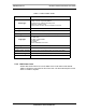
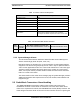
Table 5.7 Alarm Code 4133 Properties
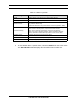
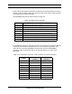
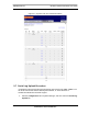
Table 5.8 Maximum BR derated TxPower
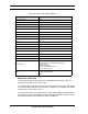
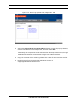
5.4.3 System Manager Alarms
The document Alarms/Events Reference Guide lists MC-Series OPM System
alarms numerically by alarm ID (0x01, 0x02, etc.).
MC-Series alarms are based on the X.733 conventions for telecommunications
equipment. The alarms are grouped by service: either “asp” for platform faults or
“iden” for iden application faults. The “cause” field contains the X.733 cause type.
“System reaction” describes the action taken by the system as a result of this
alarm, and “repair actions” provides details on what corrective action should be
taken as a result of this alarm.
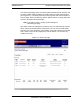
The Alarm details on the active alarm manager page of System Manager provides
additional information with respect to the board, slot number, MAC address and
equipment type.
5.5 RadioBlade Transceiver Alarm Handling
The iDEN RadioBlade transceivers Cabinet various faults and reports to the
RadioBlade controller. These faults are monitored, and if the rate at which these
faults occur surpasses a threshold, the RadioBlade transceiver (blade) is locked. The
blade will generate these faults as the result of normal actions such as re-syncing the
Event Description
IIOF Alarm Code 4133
Event Type iDEN
Severity Major
Cause Configuration Customization Error.
System reaction Set the default TX power to 9.2.
Additional Info Session ID
Repair Action
In a configuration where the number of carriers per sector
exceed six, the default TX power can’t exceed 9.2.
Reconfigure the default TX power to a value of 9.2 or less.
MC-
Series
Max # Of
Carriers/
Sector
Max Power Output per Carrier @ 6
carriers with defaultTxPower set to 9.5
New de-rated Power at 9.2
OPM 12 2W 1W