
User's Manual


MC-Series Outdoor Pole Mount Users Guide
998-5005-01 Rev X1
5-6 ©2007 RadioFrame Networks, Inc. MC-Series
CONFIDENTIAL AND PROPRIETARY
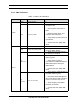
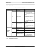
Table 5.3 OPM RF Shelf LED Indications
5.4 Software Alerts
System Manager Alarms
The MC-Series OPM System provides fault alarming and isolation within System
Manager for individual components, which consists of detecting catastrophic faults
that prevent a component from responding to a periodic “ping”. Depending on the
severity, alarms are sent to the OMC via the iSCIII.
The Alarms/Events Reference Guide, included on the MC-Series CD and available
on the RadioFrame Networks website, lists the alarms by ID code.
All alarms passed to the OMC use the IIOF Alarm Code 35009, which uses the event
description “Unable to key BR”.
5.4.1 Viewing System Manager Alarms
1. Select the Alarms tab in System Manager to display the Active Alarm Manager.
LED Indication Condition Corrective action
POWER
green normal condition none
not lit no power to RF shelf
• Verify that RF circuit breaker on PDU
is ON.
• Check power connection to PDU.
• Measure power input, and compare
with tolerances.
• Verify that the power source is
operational.
• Contact the TAC: (800) 328-0847
ALARM
green normal condition
• none
not lit not receiving power
• Verify power to RF Shelf (see
“POWER” above).
red alarm condition
• Check the Alarm Manager for:
RF SHELF MINOR, replace fan.
RF SHELF MAJOR, replace RF shelf.
• Contact the TAC: (800) 328-0847