
User's Manual


MC-Series Outdoor Pole Mount Users Guide
998-5005-01 Rev X1
1-12 ©2007 RadioFrame Networks, Inc. MC-Series
CONFIDENTIAL AND PROPRIETARY
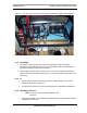
1.3.7 EAS Alarm Cabling
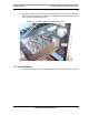
1. Follow IIOF’s procedure for routing the two 50-pair alarm cables through the
rear of the Cabinet, as shown in Figure 1.7.
2. Connect the two 50-pair alarm cables to the back of the EAS:
EAS: USER ALARM / CONTROL
EAS: SYSTEM ALARM / CONTROL
3. Terminate the two 50-pair alarm cables to the two blocks on the backboard,
making sure that each cable is connected to its specific block.
1.3.8 RF (Tx / Rx and Rx diversity)
The MC-Series OPM system Cabinet provides the following RF connectors at the
rear of the enclosure for connection to the site RF distribution system:
•Tx / Rx
•Div1
Connect the female N-type connectors to the onsite RF distribution system
(antenna, DAS, etc.).
1.3.9 Power
1. Connect the powerplant to the PDU using two (2) -hole terminal lugs. Type is
Panduit 2-hole, P/N LCD6-14A, or equivalent. Crimp tool needed: CT-1700.
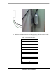
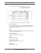
1.3.10 Air Conditioning
The enclosure’s air conditioning (A/C) system is connected to the power supply
via a three wire cable that is routed through a conduit on the side of the enclosure
(Figure 1.8).
The A/C specifications appear in Table 1.4.
Note: The air conditioning unit requires 220 Volts AC.
Warning
Verify that all breakers in the PDU are in the OFF position prior to proceeding.
Leave them in the OFF position until instructed otherwise.