
User's Manual


MC-Series Outdoor Pole Mount Users Guide
998-5005-01 Rev X1
F-2 ©2007 RadioFrame Networks, Inc. MC-Series
CONFIDENTIAL AND PROPRIETARY
• The RadioBlade transceiver under test must be in the active state and unlocked
(UEA).
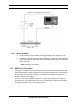
F.3 Test Tool
• Signal generator (sig gen)
A Motorola R2660 Communications Analyzer can be used as the source of the test
signal for the MC-Series OPM System during the BER test.
F.4 Testing Strategy
In the MC-Series OPM System as in the Motorola Enhanced Base Transceiver
Station (EBTS), BRs are identified by Cabinet and position, with frequencies
assigned in the datafill. BRs in the MC-Series are logical instances that map to
physical RadioBlade transceivers. The MCRB transceivers can be mixed in a
system (on a single DRBS) and the MCRB can operate in a Quad BR configuration.
Like the EBTS, the MC-Series OPM System can be organized as a single sector
(Omni), or as two or two sector site.
The basic BER testing strategy is to record the Base Radio (BR) and corresponding
RadioBlade configuration of the MC-Series OPM System, and then test each blade
across the power spectrum in its assigned range(s) of frequency.
F.4.1 BER Test on an MCRB
Because the MCRB supports up to six carriers, the BR to RadioBlade transceiver
ratio can range from one-to-one up to six-to-one. BER testing confirms the
functionality of the blade hardware itself at selected frequencies and sensitivity
levels, allowing you to check functionality specifically in the assigned ranges.
The MCRB can be viewed as a broadband RadioBlade transceiver in which up to
six iDEN carriers are set up in a 1.25 MHz band centered at an optimal
frequency. When testing an MCRB transceiver, the BER test start page allows an
optional center carrier to be entered. By default, if only a carrier (no center
carrier) is specified for the BER test, the test will be done at that specified carrier,
with the band centered on the specified carrier. Entering both a carrier and a
center carrier allows BER testing to be done at non-center carriers.
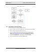
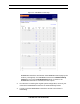
The procedures in this guide cover BER testing of the full complement of
RadioBlade transceivers. The BER testing methodology proceeds from sector to
sector, testing each Cabinet shelf and position in succession. Figure F-1
summarizes the process.