
User's Manual

MC-Series Outdoor Pole Mount Users Guide998-5005-01 Rev X1
MC-Series ©2007 RadioFrame Networks, Inc. 1-5
CONFIDENTIAL AND PROPRIETARY
1.1.2 EAS
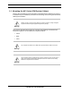
Note: You need to install an EAS. Therefore, follow this
procedure:
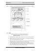
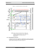
1. While supporting the EAS, slide the EAS into the Cabinet mounting position.
2. Mount the EAS in the location shown in Figure 1.1.
3. Secure the EAS to the Cabinet mounting rails using the four mounting screws
provided with the unit. Tighten the screws to 4.5 Nm (40 in-lb).
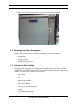
4. Connect the RadioFrame Networks-provided ground cable (P/N 820-0609-10;
EAS to GND BAR) between the Cabinet ground bar and the grounding lug on
the rear of the EAS, and ensure the connection is tight.
5. Connect the RadioFrame Networks-provided power cable (P/N 820-0616-50;
EAS to PDU-EAS) between the EAS power and the EAS circuit breaker on the
PDU.
6. Connect EAS to each iSCIII according to IIOF’s installation procedure.
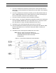
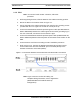
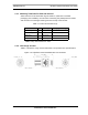
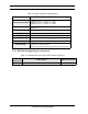
7. Refer to Figure 1.3. Connect the RadioFrame Networks-provided contact
closure alarm wires from the CONTROL port on the EAS (RJ-45) to the
STATUS connectors on the PDU (Molex).
Figure 1.3 Connection between EAS Control Port and PDU Status Connectors
Note: Figure 1.3 does not show all cabling. For
complete cabling information, refer to Appendix C
(OPM iDEN Microcell Cabinet Stack-Up
Configuration).