
User's Manual


MC-Series Outdoor Pole Mount Users Guide
998-5005-01 Rev X1
MC-Series ©2007 RadioFrame Networks, Inc. C-1
CONFIDENTIAL AND PROPRIETARY
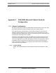
Appendix C OPM iDEN Microcell Cabinet Stack-Up
Configuration
C.1 Cabinet Configuration
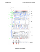
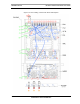
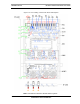
MC-Series OPM system cables are labeled with their terminuses at each end. They
are routed, dressed and secured along the side of the system Cabinet.
This appendix gives representations of intra-Cabinet cabling for your reference.
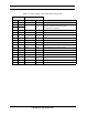
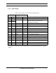
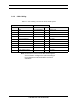
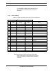
Table C.1 through Table C.9 list the connections for each component in the fully
populated MC-Series OPM system. Figure C-1 through Figure C-9 show power, RF
and data path connectivity for the system.
Cables are shown splayed for clarity. The tables, which provide references for all
connections, are keyed to the figures by Index codes. Please note that the Index
codes have significance only within this appendix and do not correspond to cable or
port labeling. Some connections are indicated in the figures only by destination
Index. This is done if cabling is very similar to connections shown, and additional
lines would clutter the diagrams.
C.1.1 Power Cabling
Power and ground cabling for a fully populated system are illustrated in Table
C.1.