
User's Manual

MC-Series Outdoor Pole Mount Users Guide998-5005-01 Rev X1
MC-Series ©2007 RadioFrame Networks, Inc. 6-15
CONFIDENTIAL AND PROPRIETARY
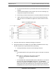
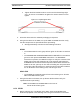
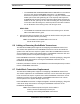
e. Tighten the blue knurled knobs on each end of the board finger tight
only—do not use a screwdriver to tighten the screws and do not over
tighten.
Figure 6.7 Replacing the BPC
5. Place the old board in the antistatic packaging for shipment.
6. Using the breakers on the PDU, turn up the ABIC and DRBS and then verify
that the components are operational before proceeding.
a. Wait approximately 3 minutes for the following indicators:
DRBS:
• The STATUS LED for each group will turn green in this order: A and then
C.
• The RADIOBLADE TRANSCEIVER STATUS LEDs will turn red and then
green for each present RadioBlade transceiver. If no RadioBlade
transceiver is present, the LED will not light. To verify the contents of the
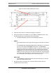
DRBS, pull out the shelf (powering off is not required) and inspect the
RadioBlade transceivers and their respective status LEDs. Reinsert the
DRBS. To do this, press up on one side rail locking arm and press down
on the other side rail locking arm, and then push the unit into the Cabinet.
For an illustration of the locking arms, refer to Figure 6.13.
ABIC CRIC
• The POWER and STATUS LEDs will turn red and then green. All other
ABIC card LEDs will turn green.
7. Using the breaker on the PDU, turn up the RF Shelf and then verify it is
operational before proceeding.
Note: The POWER and ALARM LEDs on the front of
the RF Shelf will turn green.
6.5.3 ERTM
1. Before replacing any card (board) in the ABIC, power down RadioFrame
Networks equipment in the following order using circuit breakers on the PDU: