
User's Manual

MC-Series Outdoor Pole Mount Users Guide
998-5005-01 Rev X1
6-10 ©2007 RadioFrame Networks, Inc. MC-Series
CONFIDENTIAL AND PROPRIETARY
ABIC CRIC:
• The POWER and STATUS LEDs will turn red and then green. All other
ABIC card LEDs will turn green.
8. Using the breaker on the PDU, turn up the RF Shelf and then verify it is
operational before proceeding. The POWER and ALARM LEDs on the front of
the RF Shelf will turn green.
9. Complete the procedures in sections 2.2 (System Setup) and Appendix D
(Functionality Test Procedures).
6.4.2 DRBS
1. Power down RadioFrame Networks equipment in the following order using
circuit breakers on the PDU:
• ABIC
• DRBS
• RF Shelf
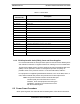
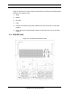
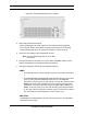
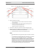
2. Disconnect cabling from the back of the DRBS to be replaced.
Refer to Appendix C (OPM iDEN Microcell Cabinet Stack-Up Configuration).
Note: Table 6.4 is indexed to the cabling figures in
Appendix C (OPM iDEN Microcell Cabinet Stack-
Up Configuration).)
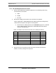
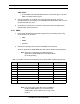
Table 6.4 Cables to be Disconnected from the Front of DRBS 1 (shown grayed out)
Note: The serial alarm cable (RF Shelf x ALARM to
DRBS ALARM INPUT x) is not used with the
OPM system. These cables may or may not be
present.
Index Disconnect From To Type
E DRBS: power
PDU: DRBS 1
power
A DRBS: ground
GND BAR
ground
N DRBS: Tx A
RF Shelf: Tx IN A
RF cable
M DRBS: Rx A
RF Shelf: Rx OUT A
RF cable
K DRBS: ALARM INPUT A
RF Shelf: ALARM
serial (See Note)
J DRBS: 10/100 RadioFrame Networks A
ABIC: ERTM PORT 1
UTP
F DRBS: 10/100 RadioFrame Networks B
ABIC: ERTM PORT 2
UTP
B DRBS: 10/100 RadioFrame Networks C
ABIC: ERTM PORT 3
UTP