
User's Manual

MC-Series System Installation & Testing
System Description
18 RadioFrame Networks, Inc.
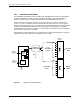
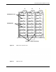
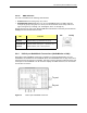
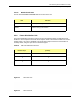
Figure 18 RBS rear view
2.2.3.1 RBS Ports
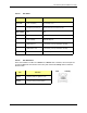
Front Ports Description
SERVICE ACCESS (A, B, C) Nextel technician local serial access
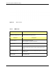
Rear Ports Description
Tx / Rx (A, B, C) Input and output for RF Shelf
(wiring depends on system configuration)
Fan (A, B, C) Power connector
ALARM INPUT (A, B, C) ALARM serial port on the back of RF Shelf 1, RF Shelf 2, and RF
Shelf 3 (respectively); provides contact closure input from RF
Shelf
10/100 RFN (A, B, C) 100Base-T Ethernet from AIC ERTM Ethernet ports 1, 2, and 3
(respectively)
REF CLOCK not currently used