
User's Manual


MC-Series System Installation & Testing
Appendix H: BER Test Procedure
RadioFrame Networks, Inc.
157
To lock a RadioBlade, select its open lock icon, and when prompted, select Accept to lock
the RadioBlade.
5 Select the Performance Monitoring tab, and verify that all BRs show the Activity State LDI.
6 On the R2660, set the 10MHz STD toggle switch to INT and power it up.
7 Connect the TOR Rx port that is being tested to the RF IN/OUT or GEN OUT port on the
R2660, depending on the desired test signal level.
8 Set the R2660 to generate an in-bound 1x6 test signal at the desired frequency and signal
level into the Rx port that corresponds to the RadioBlade or group of RadioBlades to be
tested.
Start at –120 dBm, and then increase in 2 dB increments until the BER drops below 2%. The
receive sensitivity value should be less than –106 dBm at 2% BER.
Then, start at –48 dBm and increase in 2 dB increments until the BER goes above 2%. The
maximum input power should be greater than –36 dBm at 2% BER.
If either of these values is not attained, the RadioBlade has failed specifications and should
be replaced.
H.2 BER Test Procedure
This procedure provides commands and responses to measure receiver BER.
1 Display the RadioBlade Statistics page, and unlock the RadioBlade that is to be tested.
Select the RBS icon on the System Configuration page, and then select the RadioBlade
Statistics link at the top of the RBS Status page. Determine which RadioBlade is to be tested,
and then unlock it by selecting its lock icon so that it is opened (unlocked). Refresh the page
every 30 seconds until the State of the RadioBlade has changed to ‘11’, approximately 3
minutes.
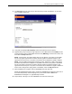
2 Select the Diagnostics tab, and then select Bit Error Rate Test.