
User's Manual


MC-Series System Installation & Testing
Scheduled and Unscheduled Maintenance
RadioFrame Networks, Inc.
99
8 Using the breaker on the PDU, turn up each RF Shelf and then verify that each RF Shelf is
operational before proceeding. The POWER and ALARM LEDs on the front of the RF Shelf
will light green.
9 Complete the procedures in sections 5.4, 5.5 and 5.6.
7.9.2.2 AIC
1
Power down RFN equipment in the following order using circuit breakers on the PDU:
• BIC
• AIC
• RBS 1 (power down RBS 2 and RBS 3 if they are present)
• RF Shelves 1,2 and 3
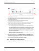
2 Disconnect cabling from the back of the chassis to be replaced.
Refer to Appendix C Cabling Diagrams: 3-Sector Configuration and Appendix D Cabling
Diagrams: Omni Configuration.
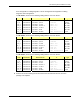
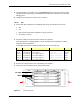
For the AIC, disconnect the following cabling from the rear of the AIC only:
Index Part Number Disconnect From To Type
P_12 820-0614-10 AIC: power PDU: AIC power
G_13 820-0609-00 AIC: ground GND BAR ground
DAT_1 111-0566-00 AIC: ERTM PORT 1 RBS 1: 10/100 RFN A UTP
DAT_2 111-0566-00 AIC: ERTM PORT 2 RBS 1: 10/100 RFN B UTP
DAT_3 111-0566-00 AIC: ERTM PORT 3 RBS 1: 10/100 RFN C UTP
DAT_5 111-0565-00 AIC: ERTM PORT 4 BIC: ERTM PORT 2 UTP
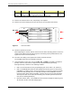
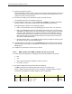
3 Remove the chassis from the rack, and package it for shipment.
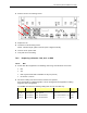
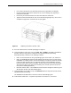
4 Remove the 4 front mounting screws (shown with arrows).
Figure 32 Front view of AIC
aBPC
PC
AIC
CRIC